Method of controlling a thermal energy harvesting system

a technology of thermal energy harvesting and energy harvesting system, which is applied in the field of vehicle, can solve the problems of large amount of engine heat and excess thermal energy typically dissipated into the atmosphere, and achieve the effect of maximizing the operating efficiency of the energy harvesting system

Inactive Publication Date: 2011-05-26
GM GLOBAL TECH OPERATIONS LLC
View PDF12 Cites 6 Cited by
  • Summary
  • Abstract
  • Description
  • Claims
  • Application Information

AI Technical Summary

Benefits of technology

[0005]A method of controlling an energy harvesting system that converts excess thermal energy from a heat source into mechanical energy is disclosed. The method includes obtaining current operational parameters of the energy harvesting system. The method further includes comparing the obtained current operational parameters to a target operating condition of the energy harvesting system to determine if the current operational parameters are within a pre-defined range of the target operating condition of the energy harvesting system. The method further includes adjusting the operation of the energy harvesting system when the current operational parameters are outside the pre-defined range of the target operating condition until the obtained current operational parameters are within the pre-defined range of the target operating conditions to maximize an operating efficiency of the energy harvesting system.

Problems solved by technology

During operation, the engine produces a large quantity of excess heat, i.e., excess thermal energy that is typically dissipated into the atmosphere and lost.

Method used


Image

  • Method of controlling a thermal energy harvesting system
  • Method of controlling a thermal energy harvesting system
  • Method of controlling a thermal energy harvesting system

Examples


Embodiment Construction

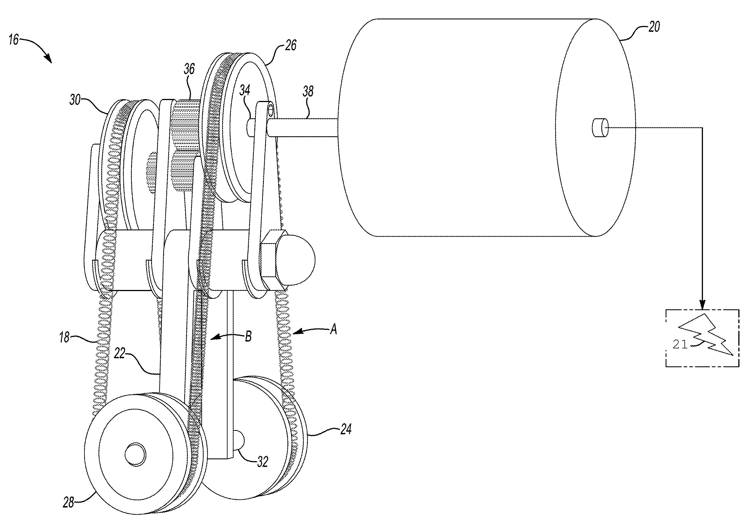
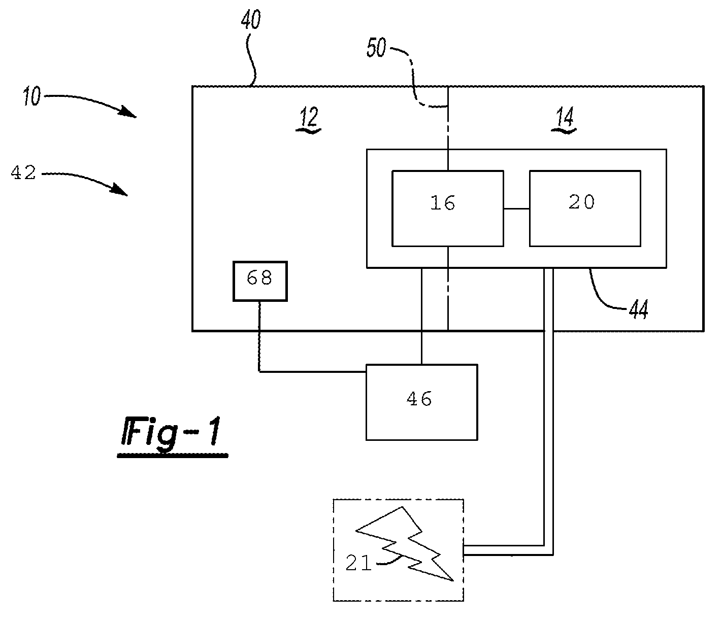
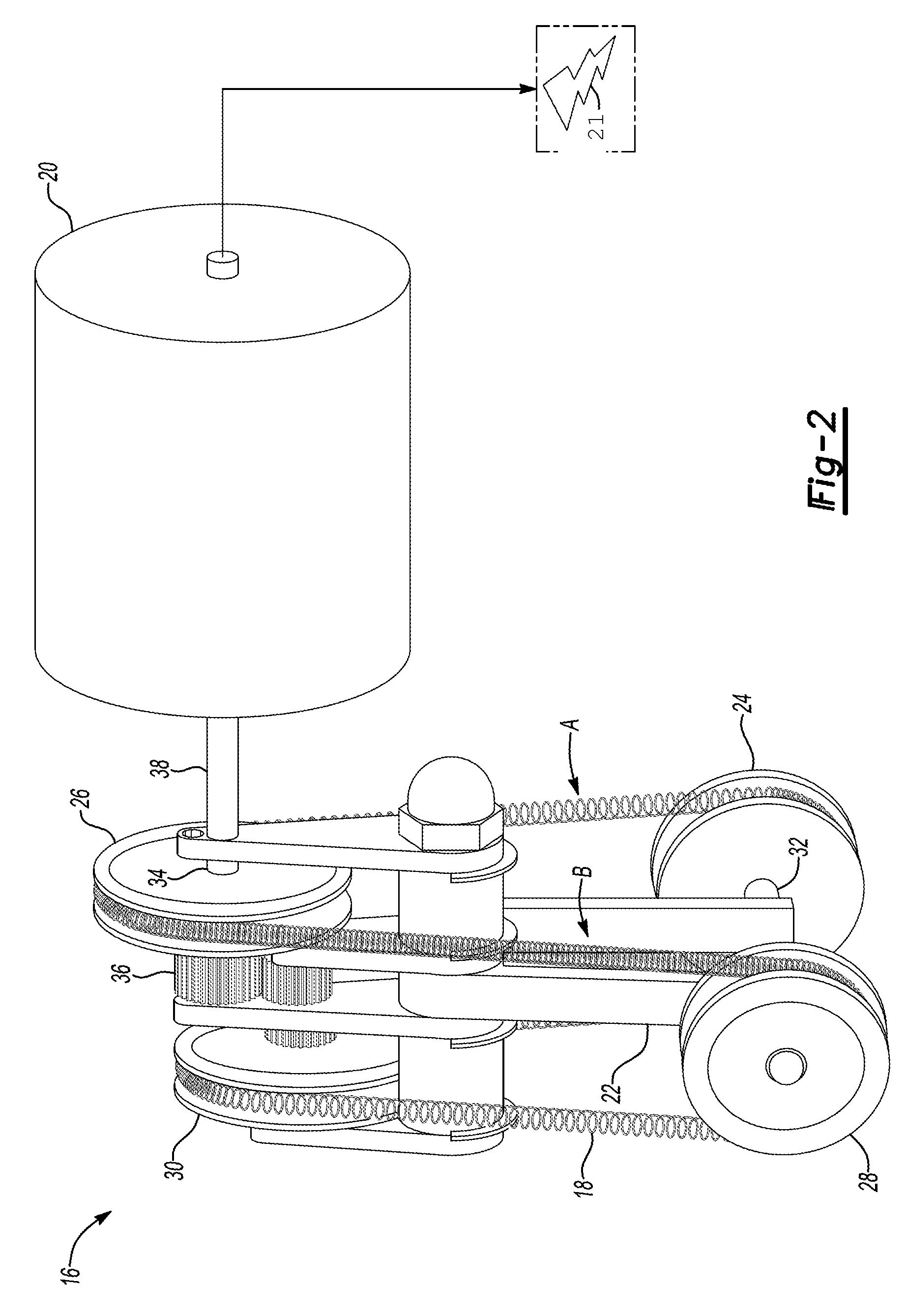
[0012]Referring to the Figures, wherein like reference numerals refer to like elements, a vehicle is shown generally at 10 in FIG. 1. Referring to FIG. 1, the vehicle 10 includes an energy harvesting system 42. The energy harvesting system 42 utilizes the temperature difference between a first fluid region 12 and a second fluid region 14 to generate mechanical or electrical energy, and therefore may be useful for automotive applications. However, it is to be appreciated that the energy harvesting system 42 may also be useful for non-automotive applications such as, but not limited to, household and industrial heating applications and geothermal heat sources.

[0013]The vehicle 10 defines a compartment 40 which may house power and drive sources for the vehicle 10, such as an engine and transmission (not shown). The compartment 40 may or may not be enclosed from the surrounding environment, although it is likely separated from a passenger compartment (not shown). Examples of the areas w...


PUM


Abstract

A method of controlling an energy harvesting system that converts excess thermal energy into mechanical energy and includes a Shape Memory Alloy (SMA) member, includes obtaining current operational parameters of the energy harvesting system, such as a maximum temperature, a minimum temperature and a cycle frequency of the SMA member. The current operational parameters are compared to a target operating condition of the energy harvesting system to determine if the current operational parameters are within a pre-defined range of the target operating condition. If the current operational parameters are not within the pre-defined range of the target operating condition, then a heat transfer rate to, a heat transfer rate from or a cycle frequency of the SMA member is adjusted to maintain operation of the energy harvesting system within the pre-defined range of the target operating condition to maximize efficiency of the energy harvesting system.

Description

CROSS-REFERENCE TO RELATED APPLICATIONS[0001]This application claims the benefit of U.S. Provisional Patent Application Ser. No. 61 / 263,177, filed on Nov. 20, 2009, the disclosure of which is hereby incorporated by reference.TECHNICAL FIELD[0002]The present invention generally relates to a vehicle, and more specifically, to a thermal energy harvesting system for the vehicle and vehicle accessories, and a method of controlling the energy harvesting system.BACKGROUND OF THE INVENTION[0003]Vehicles are traditionally powered by an engine, which powers the vehicle and provides the power to charge a battery of the vehicle. The battery provides power for starting the engine and for operating various vehicle accessories. During operation, the engine produces a large quantity of excess heat, i.e., excess thermal energy that is typically dissipated into the atmosphere and lost.[0004]Advancements in technology and desire for driver conveniences have increased the number of vehicle accessories,...

Claims


Application Information

Patent Timeline
Patent Type & Authority Applications(United States)
IPC IPC(8): F01B29/10
CPCF03G7/065F01B29/10
Inventor ALEXANDER, PAUL W.BROWNE, ALAN L.JOHNSON, NANCY L.USORO, PATRICK B.MANKAME, NILESH D.GAO, XIUJIEMC KNIGHT, GEOFFREY P.HENRY, CHRISTOPHER P.
Owner GM GLOBAL TECH OPERATIONS LLC
Why Eureka
Try Eureka