Radiant heating arrangement with distortion compensation

Active Publication Date: 2011-05-26
WS WARMEPROZESSTECHN
View PDF29 Cites 16 Cited by
  • Summary
  • Abstract
  • Description
  • Claims
  • Application Information

AI Technical Summary

Benefits of technology

[0011]The joint axis of the pivot bearing preferably extends in horizontal direction. As a result of this, the end of the radiant heat tube held in the sliding bearing may be slightly raised or lowered, without damaging forces acting on the radiant heat tube.
[0012]Furthermore, it is possible to configure

Problems solved by technology

On the other hand, they are

Method used


Image

  • Radiant heating arrangement with distortion compensation
  • Radiant heating arrangement with distortion compensation
  • Radiant heating arrangement with distortion compensation

Examples


Embodiment Construction

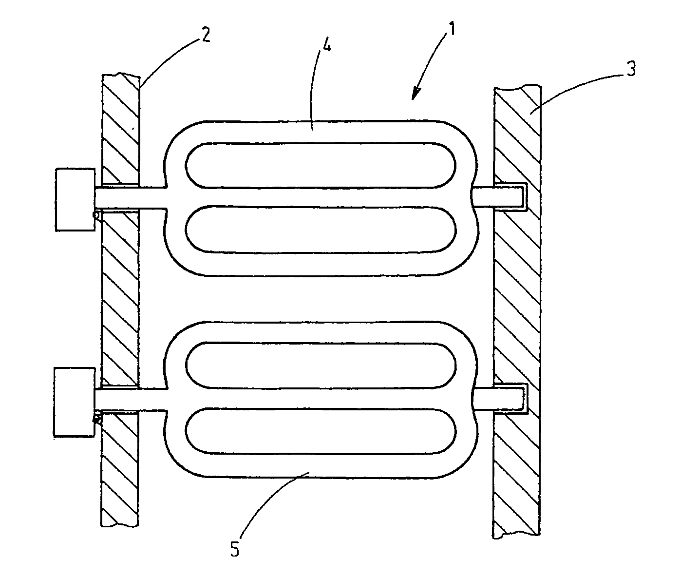
[0022]FIG. 1 shows a furnace chamber 1 that is delimited by two furnace chamber walls 2, 3. The furnace chamber 1 may be an elongated channel or tunnel, through which extend the radiant heat tubes 4, 5, each of said tubes preferably displaying the same relative transverse configuration and being arranged in a row. They are disposed to heat the furnace chamber as well as, in particular, appropriate stock to be treated, for example, a sheet metal web that is being passed in longitudinal direction through the furnace chamber.

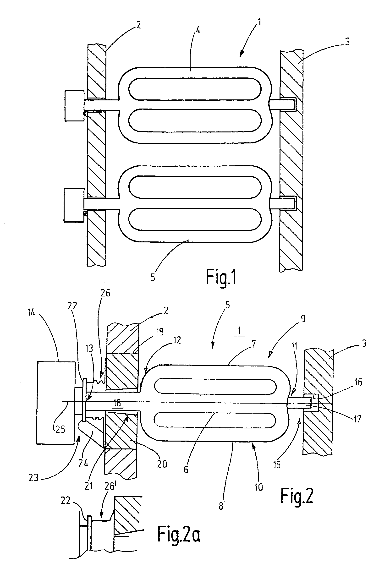
[0023]As is obvious from the example of the radiant heat tube 5 in FIG. 2, the radiant heat tubes 4, 5 are supported on both furnace walls 2, 3. Preferably, said tube consists of sheet steel and has a tube-shaped, preferably straight, center section 6 and recirculating sections 7, 8 that form loops 9, 10 with the center section 6. Such radiant heat tubes 4, 5 are also referred to as “double-P radiant heat tubes”. These tubes are closed on one end 11, while they are...


PUM


Abstract

A radiant heat tube (5) comprises a tube body having a center section (6) and at least one recirculating section (7, 8) arranged next to the center section, said recirculating section forming a loop (9, 10) with said center section. A pivot joint bearing (23) is arranged on one end (12) of the radiant heat tube, while a sliding bearing (15) is arranged on the other end (11) of the radiant heat tube, said sliding bearing (15) being arranged opposite said pivot joint bearing (23). A burner (14) is disposed to heat the radiant heat tube (5).

Description

CROSS-REFERENCE TO RELATED APPLICATION[0001]This is a continuation-in-part application of pending international application PCT / EP2009 / 004850 filed Jul. 3, 2009 and claiming the priority of German Application No. 20 2008 009 065.2 filed Jul. 4, 2008.BACKGROUND OF THE INVENTION[0002]The invention relates to a radiant heat tube that is also briefly referred to as a radiant tube.[0003]Radiant heat tubes are used for heating furnace chambers, whereby said tubes are internally heated by a suitable heat source, for example, a burner, and heat up in doing so. Stock located in a furnace chamber is predominantly heated by thermal radiation emitted by the radiant heat tube.[0004]In industrial applications, radiant heat tubes having several arms or branches are used, these having a considerable overall weight. One end of the radiant heat tube extends through a furnace wall. On the outside, a burner is usually attached by flanges. In order to absorb the considerable weight of the radiant heat t...

Claims


Application Information

Patent Timeline
IPC IPC(8): F24C3/04F27D99/00
CPCF23C3/002F23C2900/03009H05B3/64F27D99/0006F27D99/0035F27D99/00F23D14/12
Inventor WUNNING, JOACHIM A.WUNNING, JOACHIM G.
Owner WS WARMEPROZESSTECHN
Why Eureka
Try Eureka