Flow control valve

a flow control valve and valve body technology, applied in the direction of valve operating means/release devices, process and machine control, instruments, etc., can solve the problems of difficulty in the flow control valve to perform the pressure compensation function, and achieve the effect of constant flow ra

Active Publication Date: 2006-03-21
SHIMADZU CORP
View PDF5 Cites 7 Cited by
  • Summary
  • Abstract
  • Description
  • Claims
  • Application Information

AI Technical Summary

Benefits of technology

[0010]In order to attain the above objects, according to the present invention, a flow control valve includes a cylindrical body having a fluid input port or orifice and a fluid output port or orifice formed in a sidewall thereof; a spool fitted in the cylindrical body for compensating a pressure; a spring contacting the spool for applying a force in an axial direction; and a flow bypass connecting the fluid input orifice and the fluid output orifice. In the flow control valve of the present invention, it is possible to maintain a constant flow rate even when pressures at a front side and a rear side of the flow control valve are changed.

Problems solved by technology

As a result, it is difficult for the flow control valve to perform the pressure-compensation function.

Method used


Image

  • Flow control valve
  • Flow control valve
  • Flow control valve

Examples


Embodiment Construction

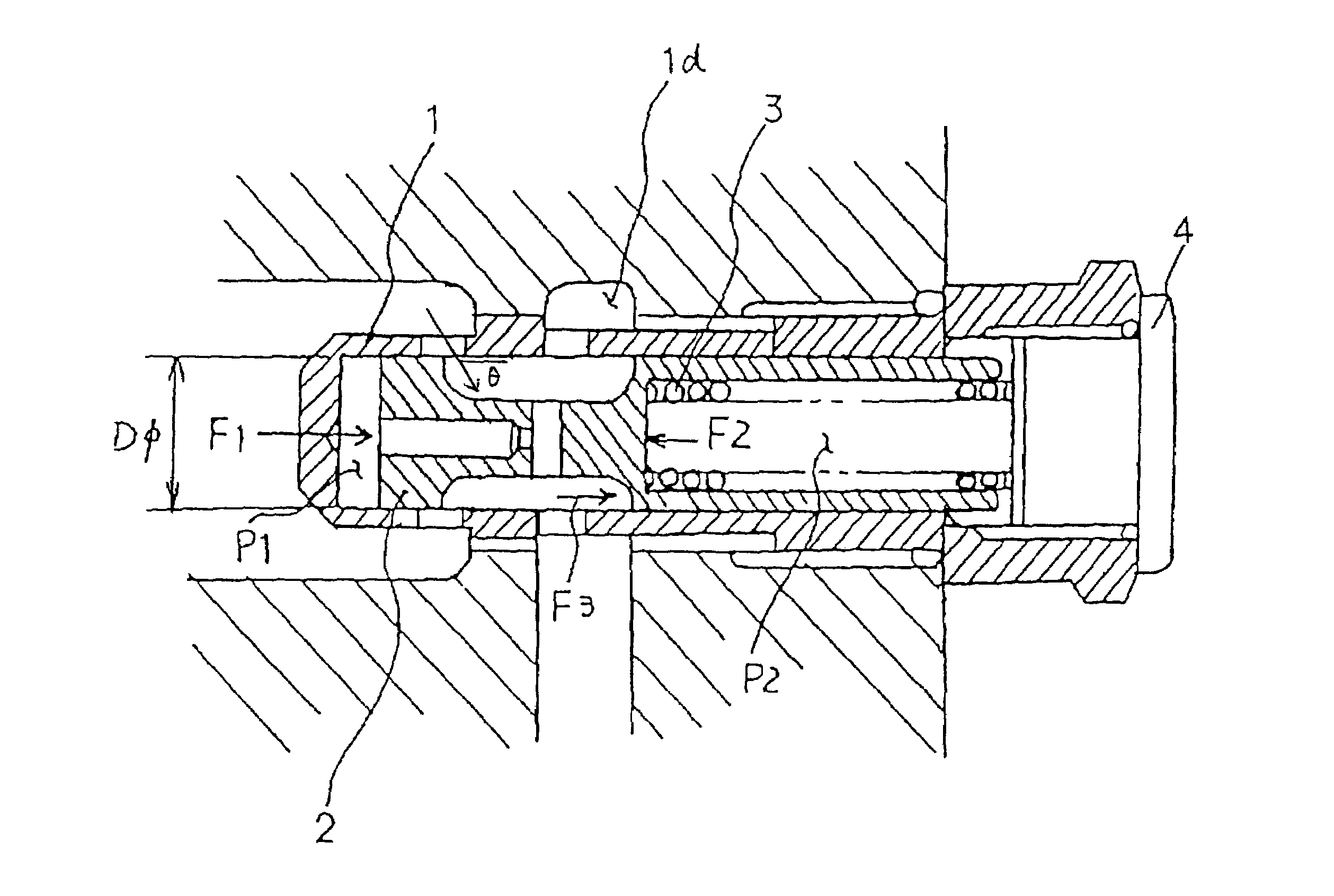
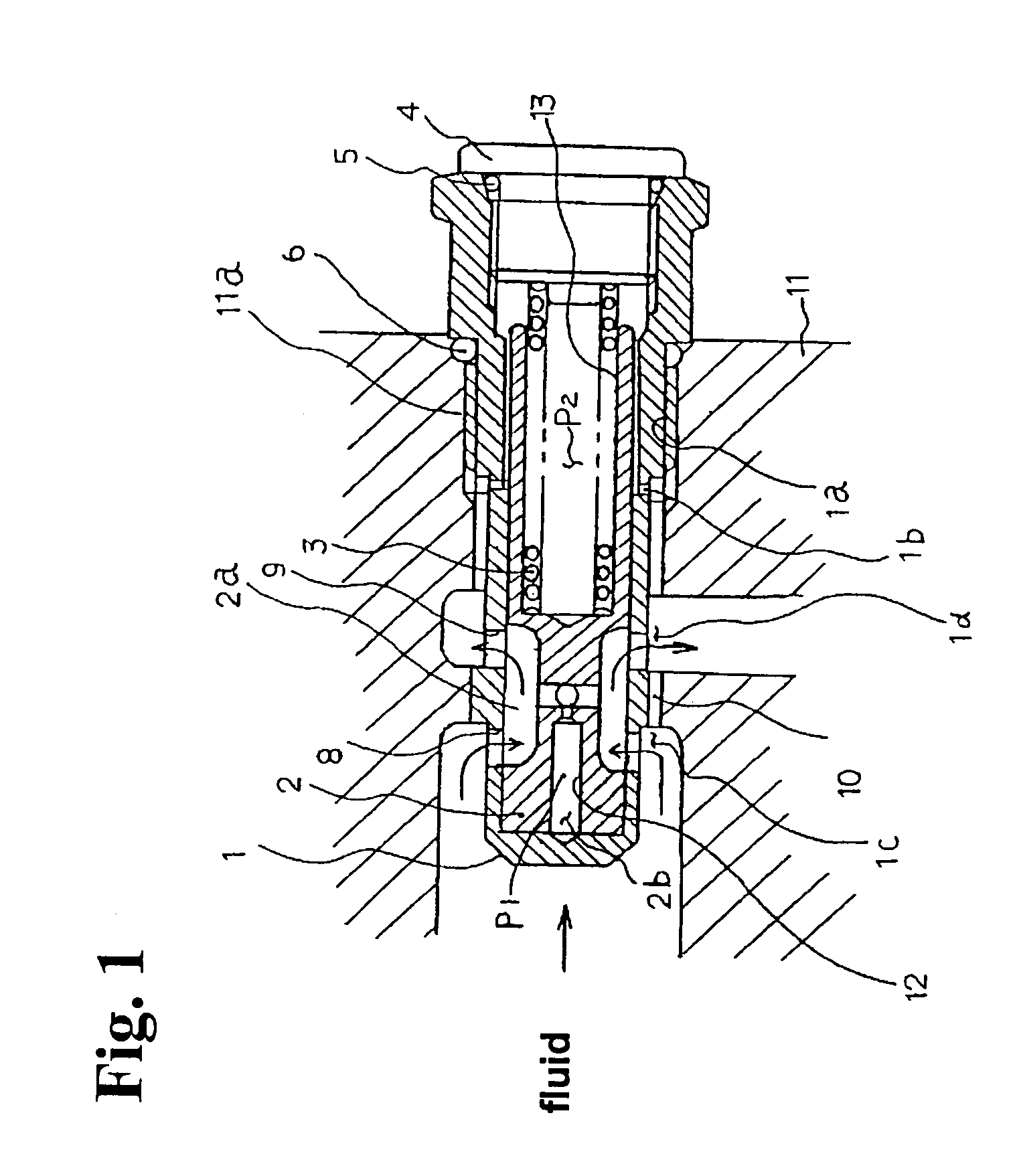
[0018]Hereunder, embodiments of the present invention will be described with reference to the accompanying drawings. FIG. 1 is a vertical sectional view showing a structure of a flow control valve according to an embodiment of the present invention. The flow control valve is to be built in a chassis block 11 of a hydraulic power unit (not shown). A spool 2 is fitted into a cylindrical body 1 to be movable in an axial direction and a spring 3 is inserted in a cylindrical portion of the spool 2. One end of the spring 3 elastically contacts the cylindrical portion of the spool 2, and the other end thereof elastically contacts an inner end surface of a plug 4 screwed to a screw portion 1a of the body 1.

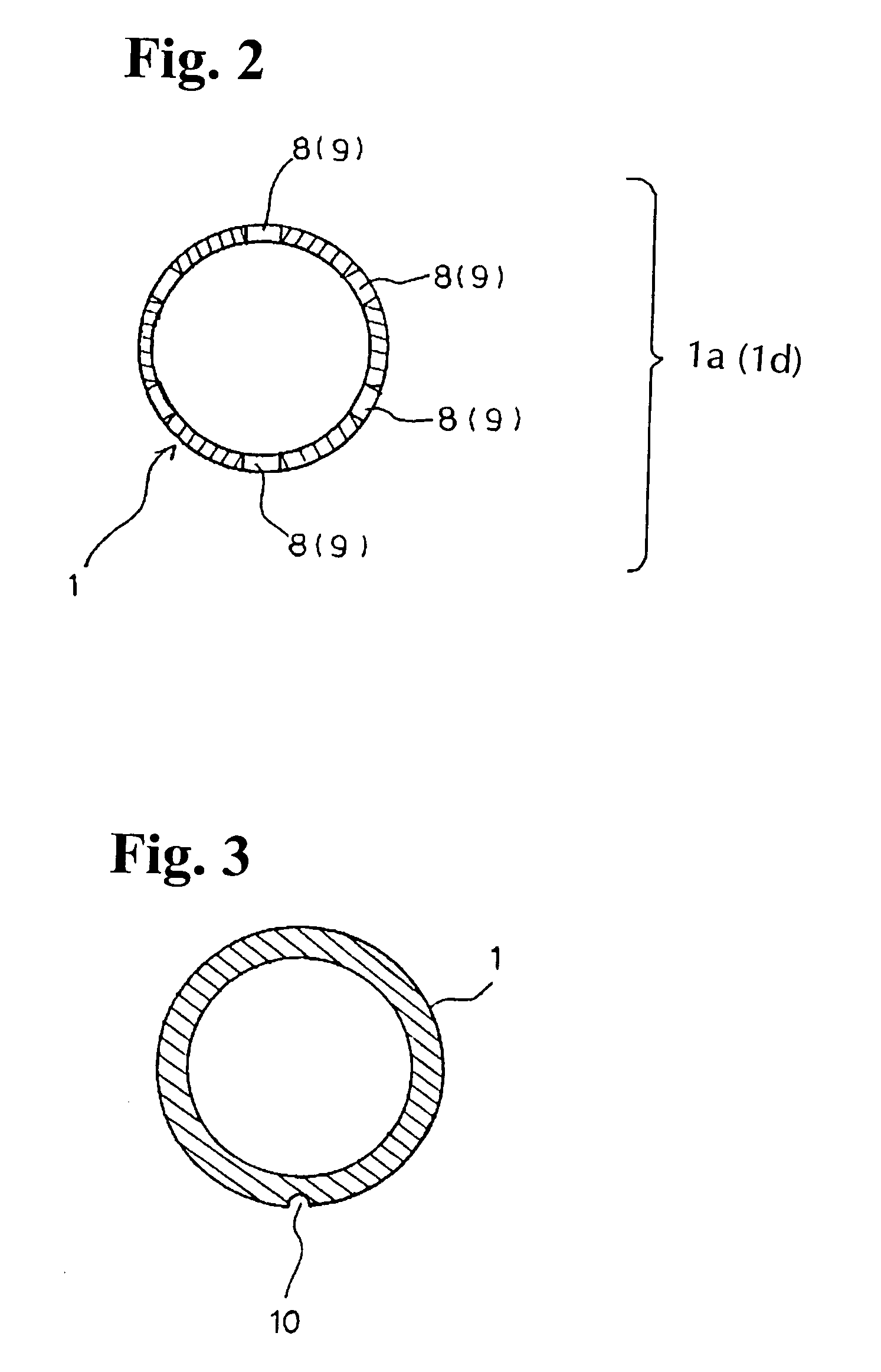
[0019]The body 1 includes the screw portion 1a to be screwed into a screw portion 11a formed in the chassis block 11; a pinhole 1b for filling a fluid into a large diameter portion 13 including the spring 3; an input port 1c formed of a plurality of orifices 8 arranged on a same circle fo...


PUM


Abstract

In a flow control valve, a spool is fitted into a cylindrical body including an input port and an output port. A spring is disposed between the spool and a flow rate setting plug at an end of the cylindrical body. A flow bypass communicating with the input port and the output port is provided on an outer peripheral portion of the cylindrical body. When a quantity of a fluid flowing through the flow control valve is reduced, the fluid flowing through the flow bypass compensates the reduction thereof. Accordingly, it is possible to maintain a constant flow rate.

Description

BACKGROUND OF THE INVENTION AND RELATED ART STATEMENT[0001]The present invention relates to a flow control valve used for various industrial instruments, for example, a hydraulically control apparatus, such as a vehicle and a forklift.[0002]Japanese Patent Publication (KOKAI) No. 5-204465 has disclosed conventional pressure compensation type flow control valves as shown in FIGS. 6 and 7. The flow control valve shown in FIG. 6 has a structure in which a spool 22 is slidably fitted in a cylindrical body 21, and a spring 24 is disposed between the spool 22 and a control screw portion 23 screwed to a base end of the body 21. When a fluid flows from an inflow port 26 to an outflow port 25 along an arrow in FIG. 6, the spool 22 performs a pressure-compensation operation for automatically controlling an opening of a throttle portion 22a formed between the spool 22 and the body 21. Accordingly, the fluid flows out of the outflow port 25 at a constant rate corresponding to an opening of a fi...

Claims


Application Information

Patent Timeline
Patent Type & Authority Patents(United States)
IPC IPC(8): G05D7/01F16K17/30F16K17/28
CPCG05D7/0133Y10T137/7613Y10T137/7788Y10T137/7793
Inventor KUROMUSHA, JUNYAYAMASHITA, SHIGERU
Owner SHIMADZU CORP
Why Eureka
Try Eureka