
Control Mechanisms and Methods of Tool-Holding Arm for Exoskeletons

a technology of control mechanism and tool holding arm, which is applied in the direction of manipulators, program-controlled manipulators, packaging, etc., can solve the problems of increasing the torque exerted on the hip of the exoskeleton, the solution is at the cost of making the exoskeleton increasingly less mobile and/or agile, and the solution is not easy to achieve. , the effect of rapid adjustmen

Active Publication Date: 2019-09-26
EKSO BIONICS
View PDF4 Cites 6 Cited by
  • Summary
  • Abstract
  • Description
  • Claims
  • Application Information

AI Technical Summary

Benefits of technology

The present invention is a device that allows for an exoskeleton-mounted, gravity-compensating tool-holding arm to be rapidly adjustable such that the tool-holding arm can quickly be mounted with different tools of varying weights, with this tool-holding arm retaining effective gravity compensation at these variable tool weights, allowing the exoskeleton wearer to easily manipulate the position of these tools without having to support the tool weight. The device also allows for the exoskeleton wearer to selectively fix the position of a tool-holding arm relative to the exoskeleton wearer, lean into the tool-holding arm so as to apply force into the tool through the tool-holding arm. Other features include improved walking mobility for an exoskeleton equipped with a hip-torque transfer device, balance of an exoskeleton equipped with an adjustable counterbalance, thermoregulation of an exoskeleton wearer, and a device that allows for the exoskeleton to provide consumables to tools or other attached devices, among others.

Problems solved by technology

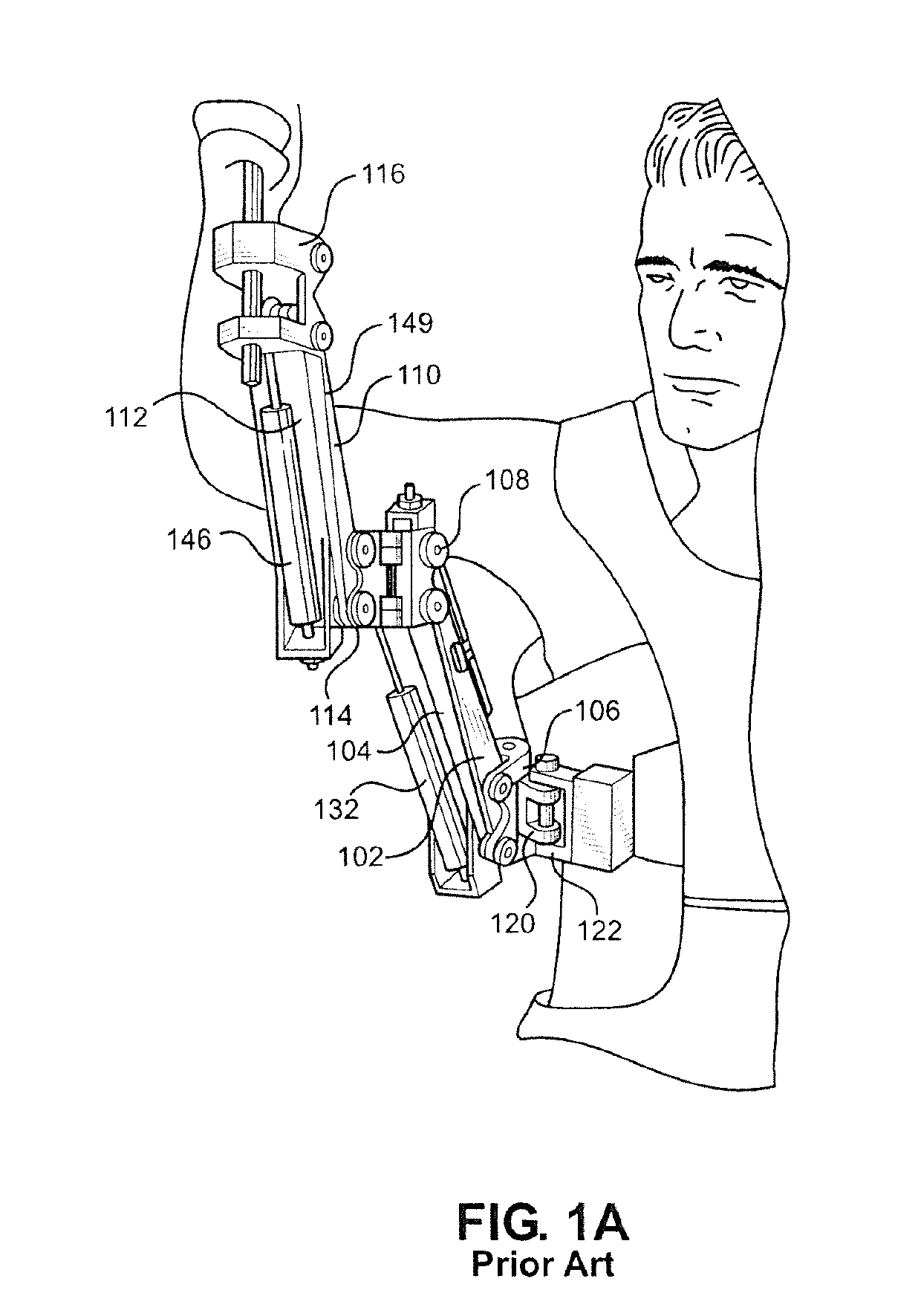
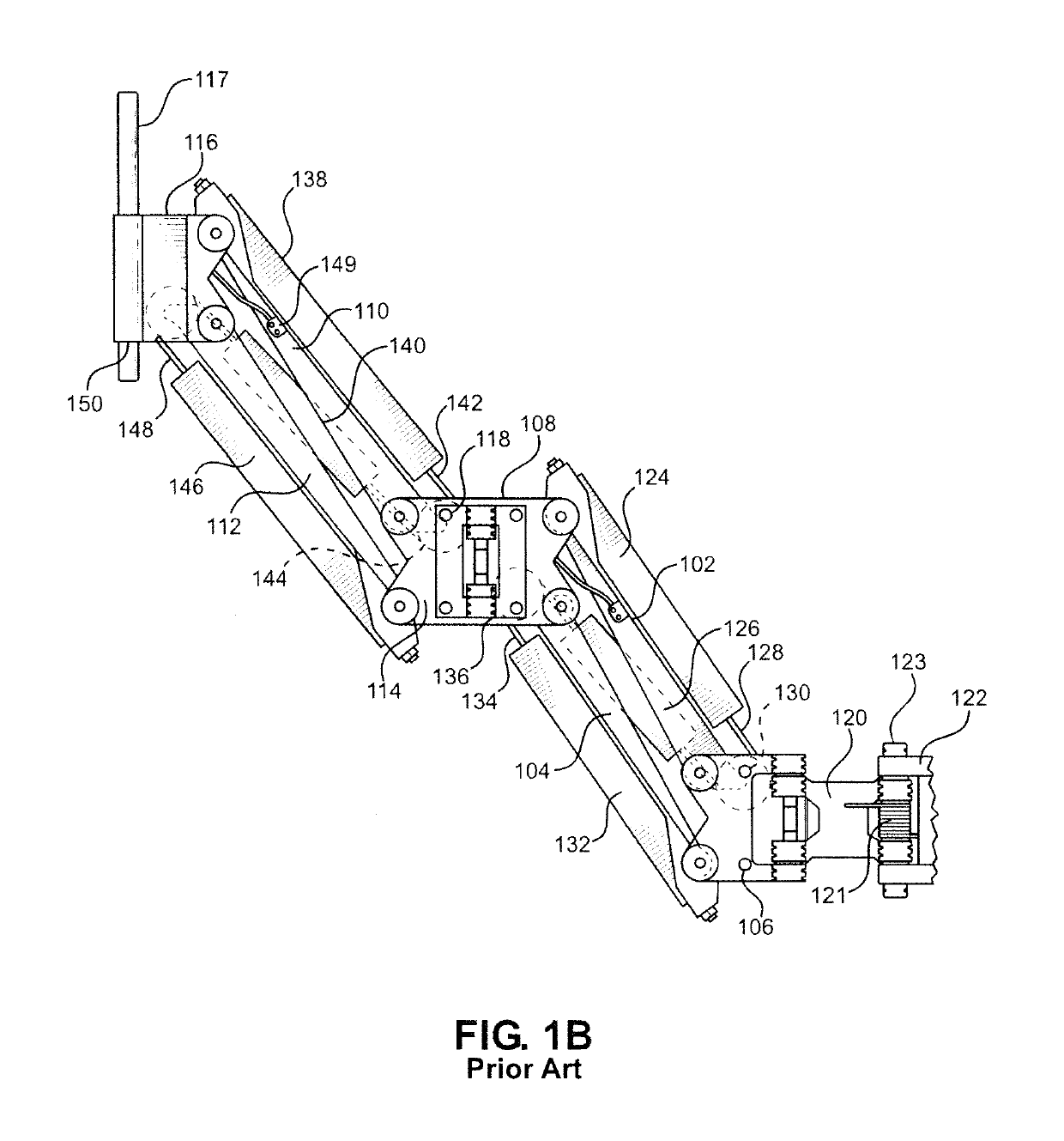
As the tool and tool-holding arm are extended further from the body of the exoskeleton wearer, the tool-holding arm will act as a lever, and the weight of the tool will result in an increasing torque being exerted on the exoskeleton hip.
To counteract this hip torque, the exoskeleton (and / or the wearer) must expend energy, and as the weight of the tool is extended away from the exoskeleton this results in a less-balanced exoskeleton that is more likely to fall over.
However, these solutions come at the cost of making exoskeletons increasingly less mobile and / or less agile, and mobility and flexibility are key functions of tool-holding exoskeletons (relative to, for example, bench / floor mounted tools or tracked vehicles).

Method used


Image

  • Control Mechanisms and Methods of Tool-Holding Arm for Exoskeletons
  • Control Mechanisms and Methods of Tool-Holding Arm for Exoskeletons
  • Control Mechanisms and Methods of Tool-Holding Arm for Exoskeletons

Examples


first embodiment

[0057]FIG. 3A shows a person 300 wearing a tool-holding exoskeleton 301 constructed in accordance with the present invention. Exoskeleton 301 is equipped with a gravity-compensating tool-holding arm 305 and is attached to exoskeleton wearer 300 by strapping 302. A hip structure 308 of exoskeleton 301 is connected to tool-holding arm 305 at a hip coupling 307, with tool-holding arm 305 connecting to and supporting the weight of a tool 303 at a tool coupling 306. Tool-holding arm 305 is composed of an upper tool arm link 309 and a lower tool arm link 310, with the tool arm links of tool-holding arm 305 being flexibly connected such that they are movable relative to each link so as to allow exoskeleton wearer 300 to use arms 304 to change the position of tool 303 relative to exoskeleton 301 and exoskeleton wearer 300. The weight of tool 303 is transferred through tool coupling 306 to upper tool arm link 309, then to lower tool arm link 310, then to hip coupling 307 and into hip structu...

second embodiment

[0061]the present invention, in which the tool-supporting arm can be selectively locked into a fixed position by the exoskeleton wearer, is shown in FIGS. 4A-E. In FIG. 4A, a person 400 is wearing a tool-holding exoskeleton 401 that is equipped with a gravity-compensating tool-holding arm 405, with exoskeleton 401 being attached to exoskeleton wearer 400 by strapping 402. A hip structure 408 of exoskeleton 401 is connected to tool-holding arm 405 at a hip coupling 407, with tool-holding arm 405 connecting to and supporting the weight of a floating tool 403 at a tool coupling 406. Tool-holding arm 405 is composed of an upper tool arm link 409 and a lower tool arm link 410, with the tool arm links of tool-holding arm 405 being flexibly connected such that they are movable relative to each link so as to allow exoskeleton wearer 400 to use arms 404 to change the position of floating tool 403 relative to exoskeleton 401 and exoskeleton wearer 400. Tool arm lock motors 422 of tool-holding...

third embodiment

[0067]the present invention, a mechanism by which the spring tension and / or rigidity in each lifting parallelogram of a gravity-compensating arm can be remotely adjusted, is shown in FIGS. 5A-E. With initial reference to FIGS. 5A and 5B, an exoskeleton wearer 500 is wearing an exoskeleton 501. A hip structure 508 of exoskeleton 501 is connected to tool-holding arm 505 at a hip coupling 507, with tool-holding arm 505 connecting to and supporting the weight of a tool 503 at a tool coupling 506. Tool-holding arm 505 is composed of an upper tool arm link 509 and a lower tool arm link 510, with the tool arm links of tool-holding arm 505 being flexibly connected such that they are movable relative to each link so as to allow exoskeleton wearer 500 to use arms 504 to change the position of tool 503 relative to exoskeleton 501 and exoskeleton wearer 500. The spring tension of each link of tool arm 505 is controlled by a remote pressure device 520, with remote pressure device 520 being mount...


PUM


Abstract

A tool-holding arm includes a plurality of links and a tool coupling that removably secures a tool to the tool-holding arm. A first fluid spring provides a gravity-counteracting force to the tool-holding arm. A locking mechanism selectively locks the first fluid spring. An adjustment mechanism selectively adjusts an amount of the gravity-counteracting force provided by the first fluid spring.

Description

CROSS REFERENCE TO RELATED APPLICATIONS[0001]This application claims the benefit of U.S. Provisional Patent Application Ser. No. 62 / 280,896, which was filed on Jan. 20, 2016 and titled “Devices for Improving the Utility of Human Exoskeletons”. The entire content of this application is incorporated herein by reference.FIELD OF THE INVENTION[0002]The present invention relates to devices and methods that augment a wearer's carrying capacity and strength, increasing performance and aiding in the prevention of injury during the execution of certain load-bearing or strength-requiring tasks. More particularly, the present invention relates to control mechanisms and methods suitable for use by a person engaging in heavy tool use or weight-bearing tasks, particularly in combination with an exoskeleton device, which potentiate improved function of the person's appendages for activities including, but not limited to, granting greater strength and endurance in the wearer's arms and allowing for...

Claims


Application Information

Patent Timeline
Patent Type & Authority Applications(United States)
IPC IPC(8): B25J19/00B25J9/00
CPCB65G47/91B25J19/0012B25J19/0016B65G2207/40F16M2200/044B65G7/12B65G2207/08B65G9/00B25J9/0006B65G2207/30
Inventor PREUSS, ADAMMEADOWS, CHRISAMUNDSON, KURTANGOLD, RUSSLUBIN, JAMESSOLANO, MARIOMASTALER, TOMFLEMING, NICHOLASSWEENEY, MATT
Owner EKSO BIONICS
Learn More