

Scanning image display apparatus
- Summary
- Abstract
- Description
- Claims
- Application Information
AI Technical Summary
Benefits of technology
Problems solved by technology
Method used
Image

Examples
first embodiment
[0040]One embodiment of the present invention will be described herein below with reference to the drawings.
[0041]First, a layout of constituent members and a shape of a scan pattern are described with regard to a scanning image display apparatus according to the present embodiment.
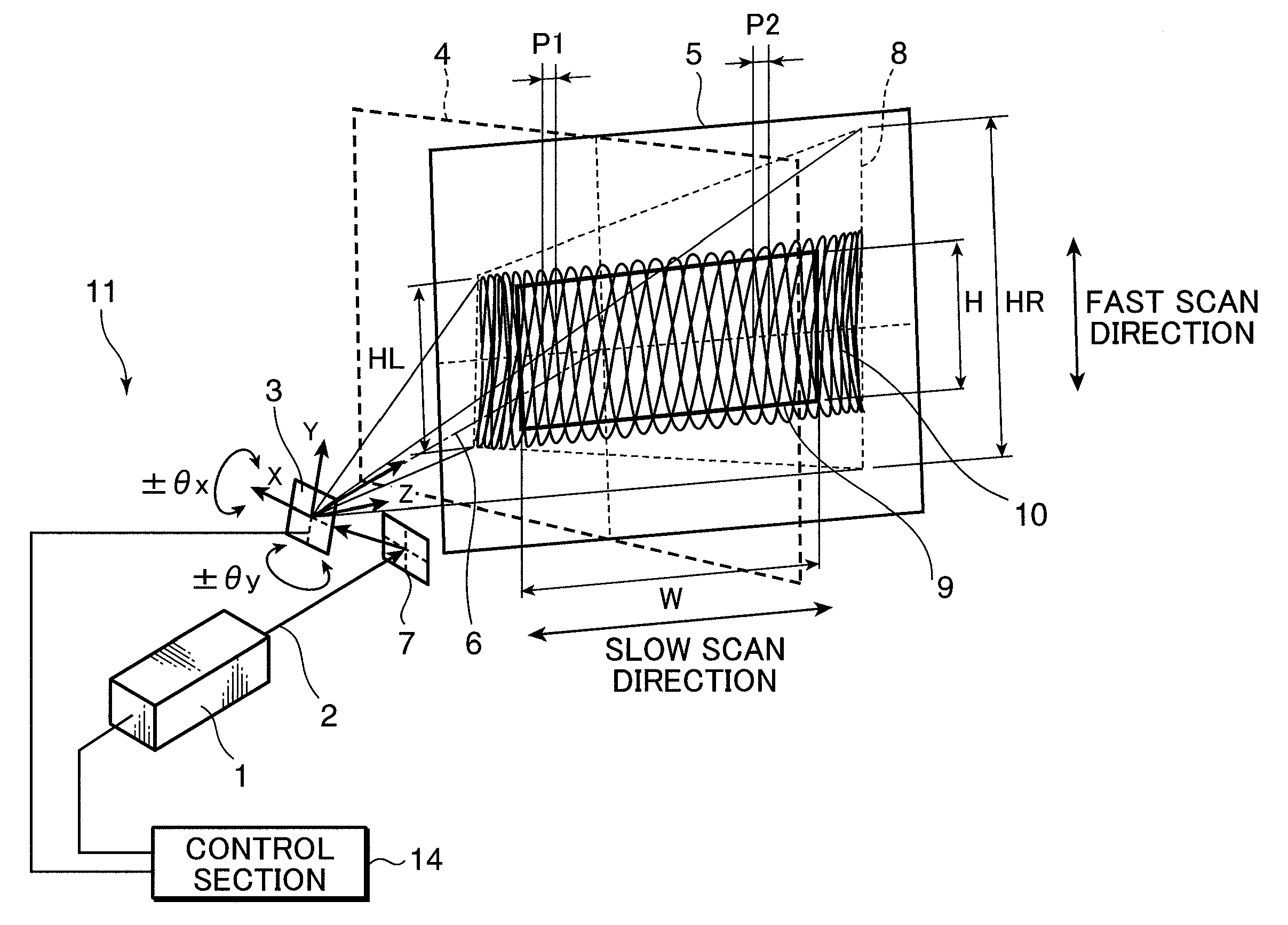
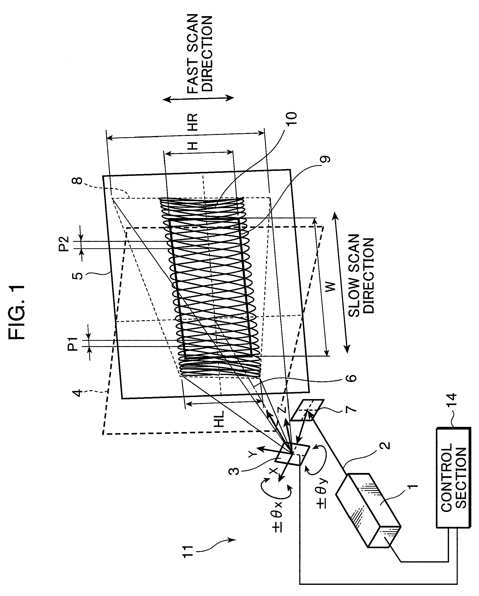
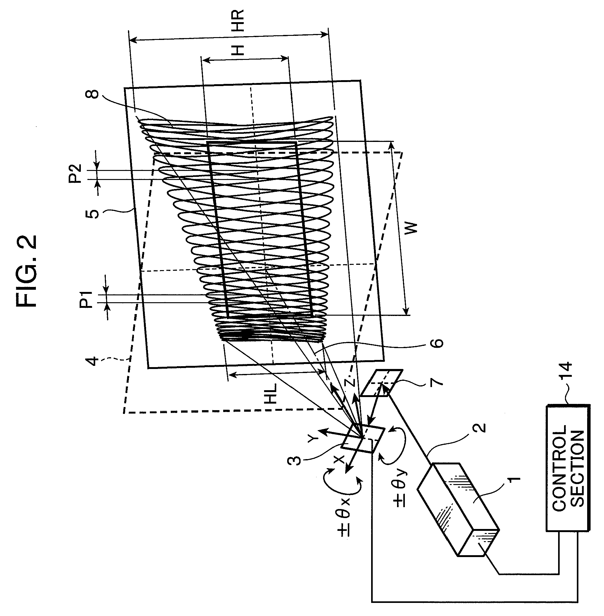
[0042]FIGS. 1 through 3 each illustrate a schematic structure of the scanning image display apparatus according to the present embodiment. FIG. 1 shows a perspective view of a scan track drawn by a driving method according to the present embodiment. FIG. 2 shows a perspective view of a scan track drawn when a conventional driving method is applied to a scanning image display apparatus which is similar in structure to that shown in FIG. 1. FIG. 3 shows a plan view of a layout regarding a scan mirror and a projection plane in the scanning image display apparatus shown in FIG. 1.
[0043]As shown in FIG. 1, a scanning image display apparatus 11 according to the present embodiment includes a light source section...
second embodiment
[0099]Next, an embodiment in which the scanning image display apparatus according to the present invention is installed in a vehicle will be described.
[0100]FIG. 7 schematically illustrates installation of the in-vehicle scanning image display apparatus according to the present embodiment. FIG. 7 shows a driving seat in an automobile seen from a rear side, and a windshield 71, a rearview mirror 72, a steering wheel 73 and the like are provided inside the automobile. In the in-vehicle scanning image display apparatus, an instrument panel section display 76 is projected from a projection opening 74 provided on a center of a dashboard onto a display region (a projection plane) formed on a rear side of the steering wheel 73. A speedometer, various indicators and the like are displayed as the instrument panel section display 76.
[0101]In the in-vehicle scanning image display apparatus, moreover, a driving seat section display 77 and a passenger seat section display 78 are projected from a...
PUM
 Abstract
Description
Claims
Application Information