Stereoscopic display unit

a display unit and stereoscopic technology, applied in the field of stereoscopic display units, can solve the problems of limited viewing position and viewing distance, small stereoscopic range (visual region), and many viewers are not able, and achieve the effects of limited small limitation of viewing position and viewing distance, and small stereoscopic rang

Inactive Publication Date: 2011-05-26
SONY CORP
View PDF33 Cites 23 Cited by
  • Summary
  • Abstract
  • Description
  • Claims
  • Application Information

AI Technical Summary

Benefits of technology

[0006]However, in the case of the parallax barrier method and the lenticular method, a stereoscopic range (visual region) is small. Thus, there is a disadvantage that viewing position and viewing distance are limited and many viewers are not able to view images at the same time. Meanwhile, in the case of the eyeglass method, limitation of vie...

Problems solved by technology

However, in the case of the parallax barrier method and the lenticular method, a stereoscopic range (visual region) is small.
Thus, there is a disadvantage that viewing position and viewing distance are limited and many viewers are not able to view images...

Method used


Image

  • Stereoscopic display unit
  • Stereoscopic display unit
  • Stereoscopic display unit

Examples


first embodiment

[0026]Basic Structure of a Stereoscopic Display Unit

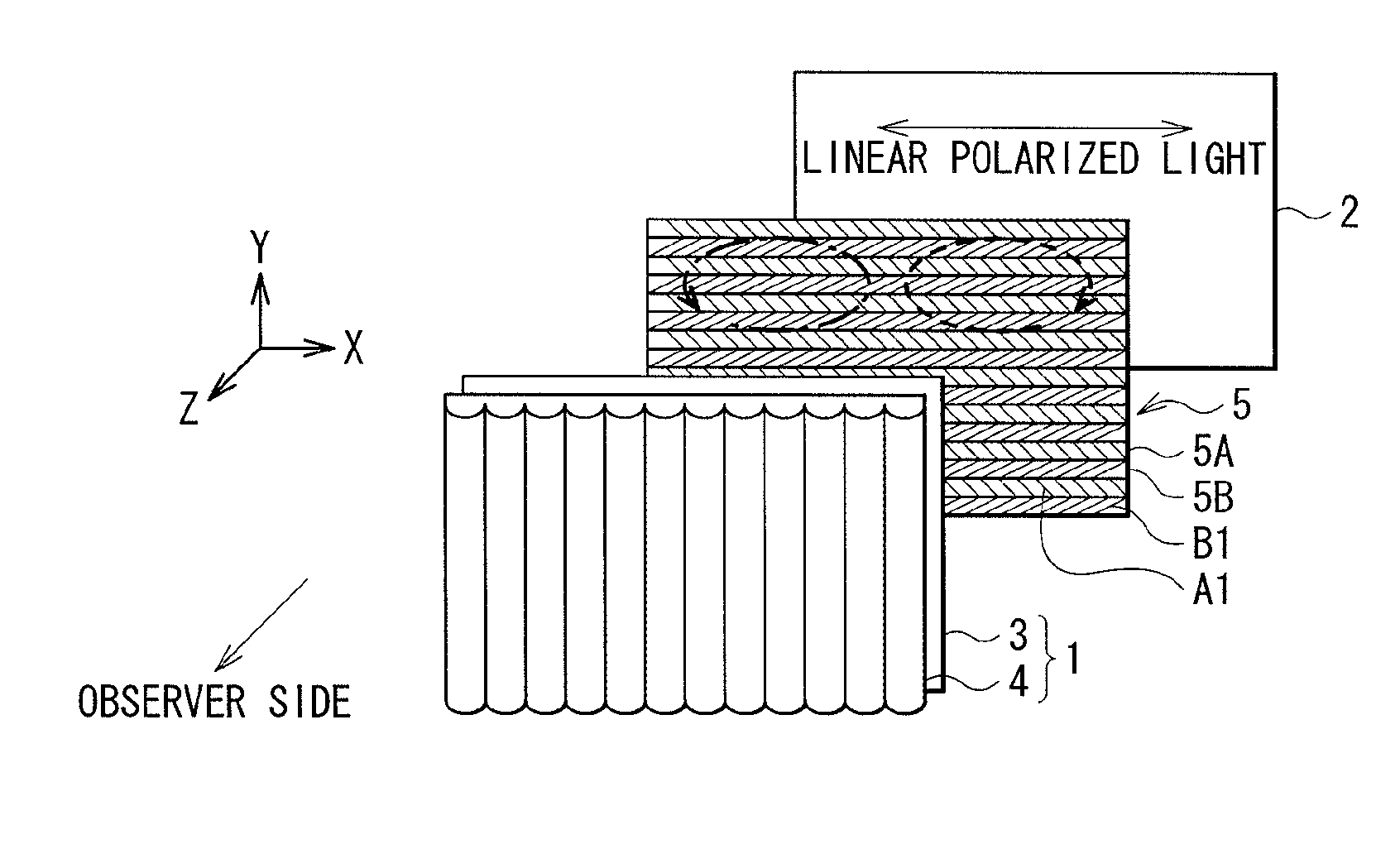
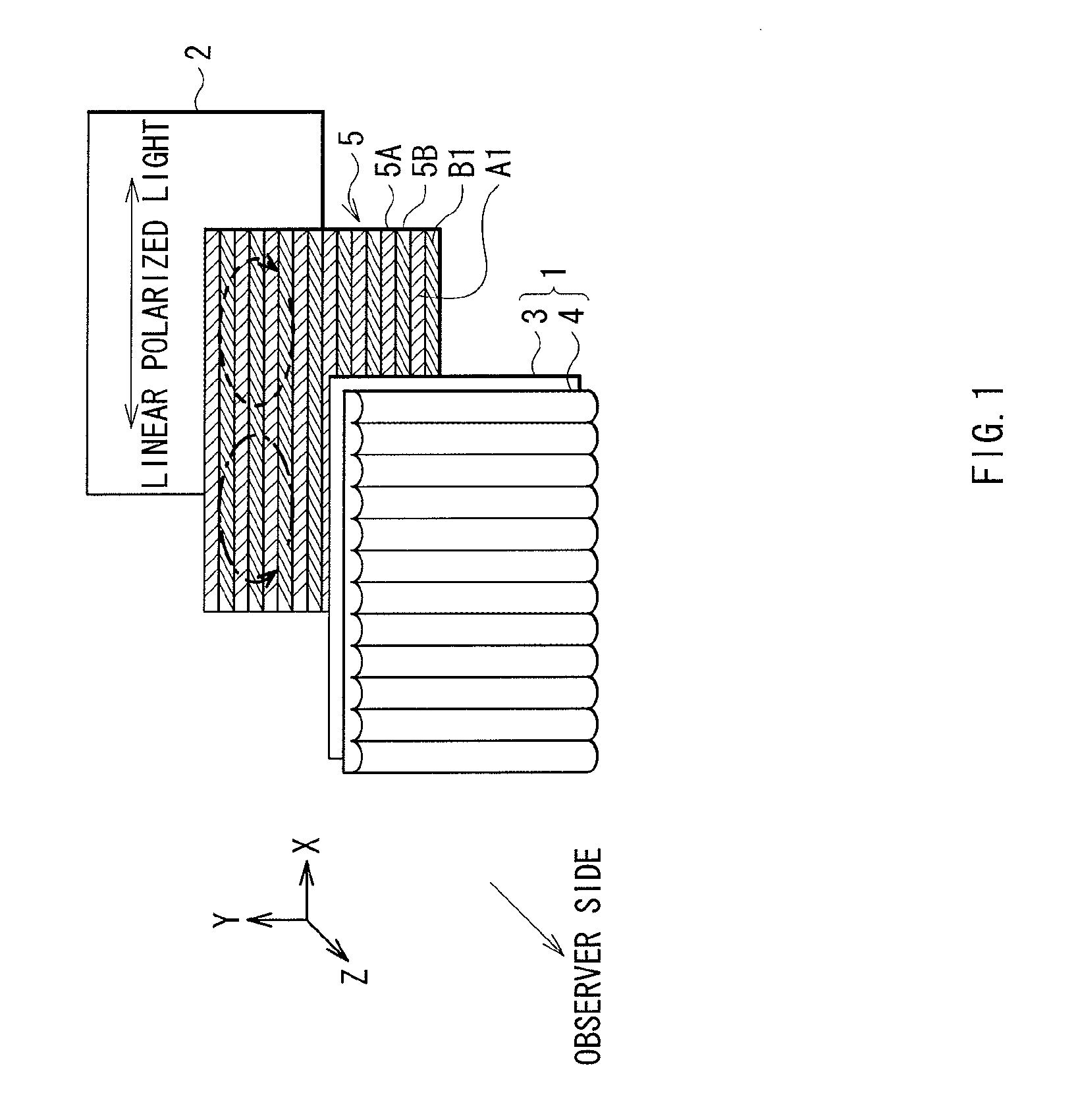
[0027]FIG. 1 illustrates a whole structure of a stereoscopic display unit according to a first embodiment of the invention. In the stereoscopic display unit, display mode is switchable between two-dimensional display mode and three-dimensional display mode, and three-dimensional display mode is switchable between naked eye method and eyeglass method. FIG. 4 schematically illustrates a state that three-dimensional display is performed by eyeglass method in the stereoscopic display unit. FIG. 5 schematically illustrates a state that three-dimensional display is performed by naked eye method. The stereoscopic display unit includes a display panel 2 as a two-dimensional display section, a polarization state conversion section 5 arranged oppositely to the display surface side of the display panel 2, and a variable lens array device 1. Further, as illustrated in FIG. 4, the stereoscopic display unit includes a polarized eyeglasses 40 use...

second embodiment

[0057]Next, a description will be given of a stereoscopic display unit according to a second embodiment of the invention. For the substantively same elements as those of the stereoscopic display unit according to the foregoing first embodiment, the same referential symbols are affixed thereto, and the description thereof will be omitted as appropriate.

[0058]FIG. 6 illustrates a structure of a variable lens array device 1A in the stereoscopic display unit according to the second embodiment. The stereoscopic display unit according to this embodiment includes the variable lens array device 1A by liquid crystal lens method instead of the variable lens array device 1 using the liquid lens in FIG. 1. The structure of this embodiment is the same as that of the foregoing first embodiment, except that the structure of the variable lens array device 1A is different.

[0059]Whole Structure of the Variable Lens Array Device 1A

[0060]The variable lens array device 1A is a variable lens array by liq...

modified example

[0067]The invention is not limited to the foregoing respective embodiments, but various modifications may be made. For example, in the foregoing respective embodiments, the variable lens array device 1 or 1A is arranged on the light exit side of the polarization state conversion section 5. However, as illustrated in FIG. 9, the variable lens array device 1 or 1A may be arranged between the display panel 2 and the polarization state conversion section 5.

[0068]Further, in the foregoing respective embodiments, in performing three-dimensional display by eyeglass method, display is performed so that the left-eye image L and the right-eye image R are alternately arranged along the vertical direction on the display panel 2. However, display may be performed in the same manner as that in the three-dimensional display by naked eye method. In other words, display may be performed so that the left-eye image L and the right-eye image R are alternately arranged along the horizontal direction on ...


PUM


Abstract

Embodiments of the invention provide an image display device that is switchable between a two-dimensional display mode, a three-dimensional display mode enabling non-autostereoscopic image display, and a three-dimensional display mode enabling autostereoscopic image display. In one embodiment, the image display device comprises a display panel operable to transmit light corresponding to image data; a polarization state conversion section comprising a first polarization segment for converting light transmitted by the display device to a first polarization state, and a second polarization segment for converting light transmitted by the display device to a second polarization state; and an optical separation element that is placed, via application of a voltage, in an on state in which light transmitted by the display panel is refracted or an off state in which light transmitted by the display panel is not refracted.

Description

BACKGROUND OF THE INVENTION[0001]1. Field of the Invention[0002]The present invention relates to a stereoscopic display unit for performing three-dimensional display by using binocular parallax.[0003]2. Description of the Related Art[0004]In the past, stereoscopic display units that realize stereoscopic vision by providing different images (parallax images) as a viewer left-eye image and a viewer right-eye image between which parallax exists. Examples of methods of such stereoscopic display units include eyeglass method and naked eye method. The eyeglass method realizes stereoscopic vision by wearing special eyeglasses for stereoscopic vision. In Japanese Patent No. 3767962, as eyeglasses for stereoscopic vision, a method using a polarization filter is disclosed.[0005]Meanwhile, in the naked eye method, stereoscopic vision is enabled with naked eyes without wearing the special eyeglasses. Examples of naked eye methods include parallax barrier method and lenticular method. In the par...

Claims


Application Information

Patent Timeline
IPC IPC(8): G06T15/00G02B30/25G02B30/27G02B30/28
CPCG02B27/2214G02B27/26H04N13/0452H04N13/0434H04N13/0404H04N13/305H04N13/337H04N13/356G02B30/25G02B30/27G02B30/28
Inventor AKITA, MASAYOSHI
Owner SONY CORP
Why Eureka
Try Eureka