Image Display Apparatus Capable of Simultaneously Displaying Plurality of Images

a technology of image display and plurality, which is applied in the field of image display apparatus capable of simultaneously displaying a plurality of images, can solve the problems of usability degradation of the image display apparatus, viewers' difficulty in understanding which image is being explained,

Inactive Publication Date: 2011-05-26
SANYO ELECTRIC CO LTD
View PDF8 Cites 16 Cited by
  • Summary
  • Abstract
  • Description
  • Claims
  • Application Information

AI Technical Summary

Benefits of technology

[0010]According to an aspect of the present invention, an image display apparatus which displays an image based on an image signal includes an input unit to which a plurality of image signals are input from a plurality of image signal supply apparatuses, a display unit which displays a plurality of images based on the plurality of image signals, respectively, in a plurality of display regions, respectively, and a control unit which controls the display unit, when not less than one display region is selected from among the plurality of display regions, such that display manners of the images to be displayed are differentiated between the selected display region and a remaining display region of the plurality of display regions other than the selected display region.

Problems solved by technology

However, in a conventional image display apparatus, in a scene where the user actually makes a presentation in the plural-screen display state as described above, the user has to manipulate an image source to turn a page of images and the like while showing a pointer with a laser pointer, which causes a problem of degradation in usability of the image display apparatus.
There has also been a problem that, when a position pointed to with a laser pointer deviates from a desired image due to influence of hand jiggling, the viewers feel it difficult to understand which image is being explained.

Method used


Image

  • Image Display Apparatus Capable of Simultaneously Displaying Plurality of Images
  • Image Display Apparatus Capable of Simultaneously Displaying Plurality of Images
  • Image Display Apparatus Capable of Simultaneously Displaying Plurality of Images

Examples


embodiment 1

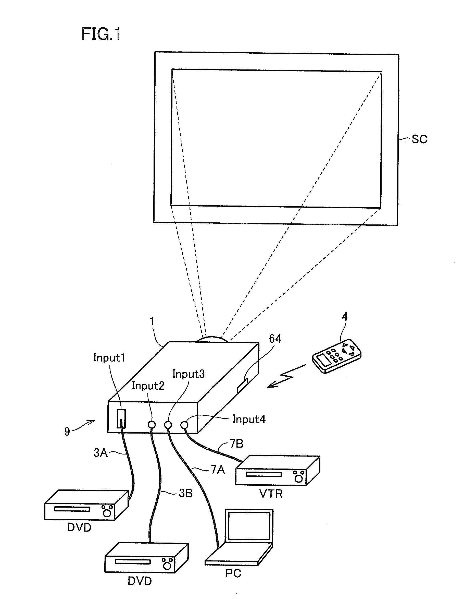
[0025]FIG. 1 is a view illustrating a configuration of peripheral apparatuses when an image is projected by an image display apparatus in accordance with the present embodiment 1.

[0026]Referring to FIG. 1, an image display apparatus (hereinafter also referred to as a “projector”) 1 in accordance with the present embodiment 1 is a liquid crystal projector projecting an image utilizing a liquid crystal device, and projects (displays) the image by projecting light of the image to be displayed by the liquid crystal device on a projection screen SC. A projection surface is not limited to projection screen SC, and may be a wall surface.

[0027]Projector 1 includes a manipulation accepting unit 64 receiving an infrared modulated remote control signal transmitted from a remote controller 4 manipulated by a user, and an input unit 9. The remote control signal includes a command signal for remotely controlling projector 1.

[0028]Manipulation accepting unit 64 can not only receive the remote cont...

embodiment 2

[0092]Since a configuration and a basic operation of a projector in accordance with Embodiment 2 of the present invention are identical to those of projector 1 in accordance with Embodiment 1, the description thereof will not be repeated by using the same reference numerals, and only image processing different from that in Embodiment 1 will now be described.

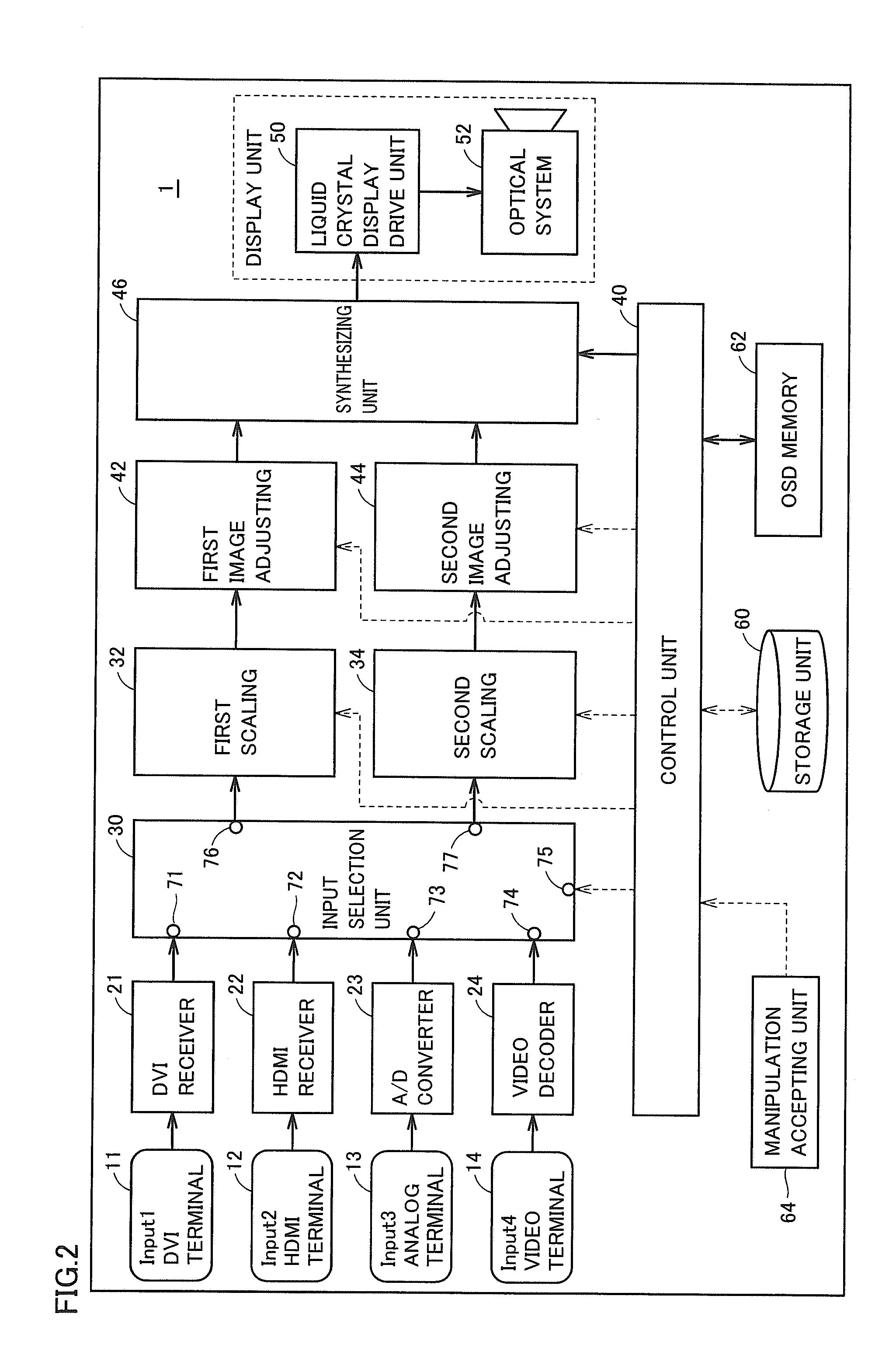
[0093]FIG. 8 is a flowchart for illustrating an operation of a projector in accordance with Embodiment 2 of the present invention. When an image signal is input to input unit 9, control unit 40 gives instructions to the units of projector 1 shown in FIG. 2 to cause an image based on the input image signal to be displayed, and operates in accordance with a processing flow of FIG. 8.

[0094]Referring to FIG. 8, in step S11, control unit 40 determines whether or not projector 1 is set to the dual-screen display mode. If projector 1 is not set to the dual-screen display mode (NO in step S11), control unit 40 causes an image based on a ...

embodiment 3

[0109]Since a configuration and a basic operation of a projector in accordance with Embodiment 3 of the present invention are identical to those of projector 1 in accordance with Embodiment 1, the description thereof will not be repeated by using the same reference numerals, and only image processing different from that in Embodiment 1 will now be described.

[0110]FIG. 11 is a flowchart for illustrating an operation of a projector in accordance with Embodiment 3 of the present invention. When an image signal is input to input unit 9, control unit 40 gives instructions to the units of projector 1 shown in FIG. 2 to cause an image based on the input image signal to be displayed, and operates in accordance with a processing flow of FIG. 11.

[0111]Referring to FIG. 11, in step S21, control unit 40 determines whether or not projector 1 is set to the dual-screen display mode. If projector 1 is not set to the dual-screen display mode (NO in step S21), control unit 40 causes an image based on...


PUM


Abstract

When a dual-screen display mode is performed, two images based on two image signals, respectively, are simultaneously displayed in display regions of a display unit. If a presenter desires viewers to focus attention on one of the two images, a projector differentiates display manners of the images to be displayed, between one display region and the other display region. For example, if the presenter desires the viewers to focus attention on one image, the projector performs image processing for causing the other image to be displayed in an unhighlighted manner. As the image processing on this occasion, if the two images are both color images, the projector converts only the other image from the color image to a monochrome image.

Description

[0001]This nonprovisional application is based on Japanese Patent Application No. 2009-267375 filed on Nov. 25, 2009 with the Japan Patent Office, the entire contents of which are hereby incorporated by reference.BACKGROUND OF THE INVENTION[0002]1. Field of the Invention[0003]The present invention relates to an image display apparatus, and more particularly, to an image display apparatus capable of simultaneously displaying a plurality of images.[0004]2. Description of the Related Art[0005]In recent years, an image display apparatus tends to include plural types of input terminals, and various image sources (external image equipment) can be connected thereto. In a case where a plurality of image signals are input from a plurality of image sources to the image display apparatus, a user can switch between a single-screen display state in which an image based on one of the plurality of image signals is singularly displayed on a substantially entire screen and a plural-screen display st...

Claims


Application Information

Patent Timeline
Patent Type & Authority Applications(United States)
IPC IPC(8): G09G5/02G09G5/00G06F3/048G06F3/0484
CPCG09G5/003G09G5/14G09G2320/066G09G2320/0666H04N9/3179G09G2340/0407G09G2340/12G09G2340/14G09G2320/0686
Inventor YASUKAWA, KEIOHFUNE, KENJI
Owner SANYO ELECTRIC CO LTD
Why Eureka
Try Eureka