Controlling Method for Ultra-sound Sensor

a control method and ultra-sound sensor technology, applied in the field of control methods for ultrasound sensors, can solve the problems of limited detection range of ultra-sound sensors, increased difficulty in correct ultra-sound receivers, and increased influence of multiple reflection effects of reflective ultra-sound waves, so as to increase the driving voltage of ultra-sound sensors and increase the reliability of detecting reflective ultra-sound waves

Inactive Publication Date: 2011-05-26
LITE ON TECH CORP
View PDF10 Cites 19 Cited by
  • Summary
  • Abstract
  • Description
  • Claims
  • Application Information

AI Technical Summary

Benefits of technology

[0008]One example of the invention is directed to a controlling method for ultra-sound sensor. When it is detected that the obstacle is very close, the driving voltage of the ultra-sound sensor will be increased so as to increase the reliability in detecting reflective ultra-sound wave.

Problems solved by technology

No matter application of one single or several ultra-sound sensors, due to the properties of the ultra-sound sensor, the detectable range of the ultra-sound sensor is restricted, especially in close distance detection.
In detection of an object in close distance, the influence of multiple reflections effect of reflective ultra-sound wave may become serious and the ultra-sound receiver has difficulty in correctly distinguishing main reflective ultra-sound wave from multi-reflective ultra-sound wave.
So, it is difficulty to perform appropriate control.
If a reflective ultra-sound wave is received within the reverberation time, the micro-processor will not be able to distinguish the reflective ultra-sound wave due to the overlap between the reflective ultra-sound wave and the emitted ultra-sound wave within the reverberation time.

Method used


Image

  • Controlling Method for Ultra-sound Sensor
  • Controlling Method for Ultra-sound Sensor
  • Controlling Method for Ultra-sound Sensor

Examples


first embodiment

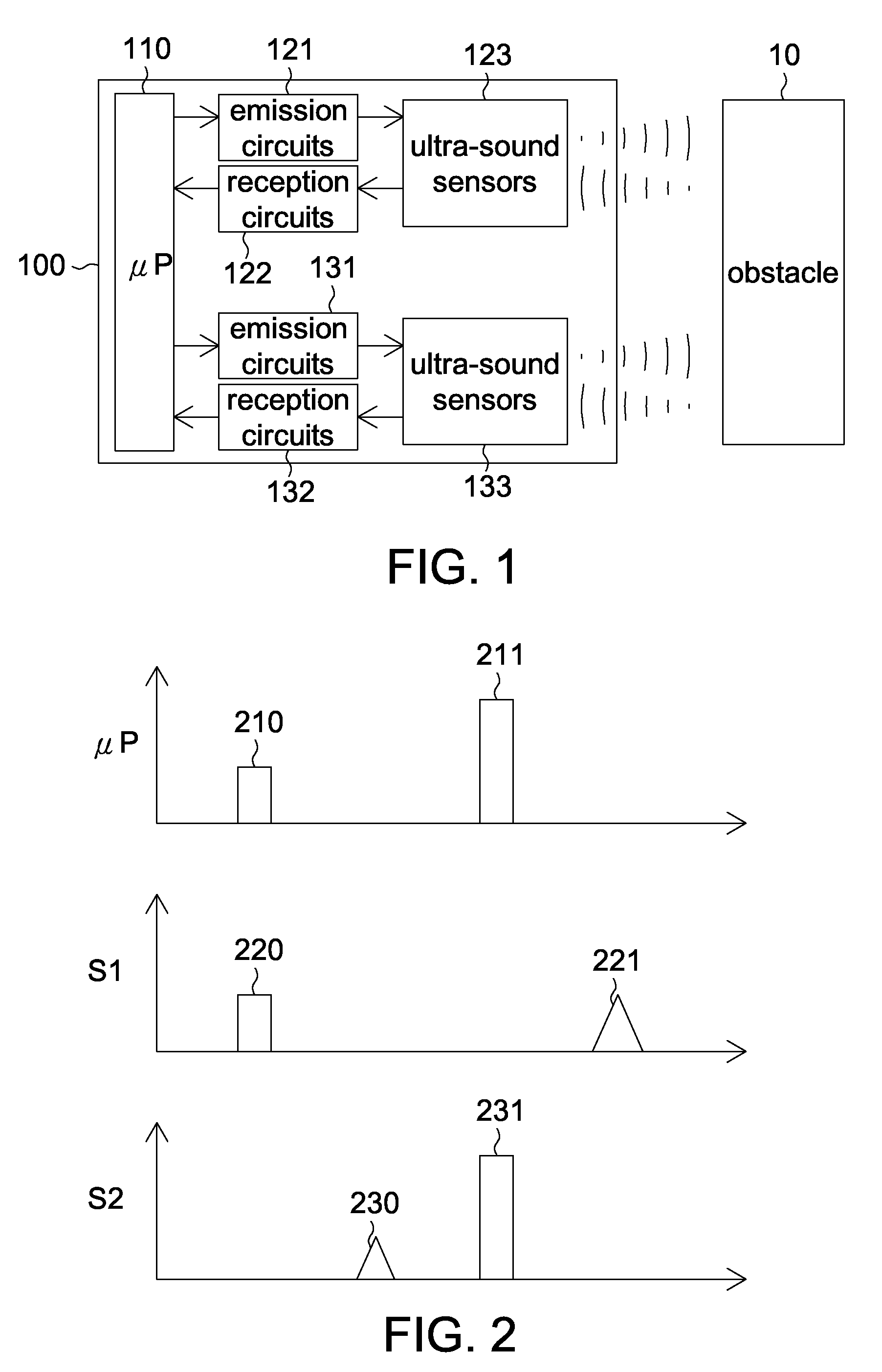
[0021]In the first embodiment of the invention, when it is detected that the obstacle is very close to the ultra-sound sensor, the driving voltage of the ultra-sound sensor will be increased to increase the detection reliability. For the convenience of elaboration, the first embodiment of the invention is exemplified by the application of two ultra-sound sensors. However, it is understood that the invention is not limited thereto. That is, the application of more ultra-sound sensors can also be adapted to other embodiments of the invention.

[0022]FIG. 1 shows a functional diagram of an electronic device according to a first embodiment of the invention. As indicated in FIG. 1, the electronic device 100 comprises a micro-processor (μP) 110, two emission circuits 121 and 131, two reception circuits 122 and 132 and two ultra-sound sensors 123 and 133. The micro-processor 110 emits a driving signal to the emission circuits 121 and 131. The ultra-sound sensors 123 and 133 are driven to emi...

second embodiment

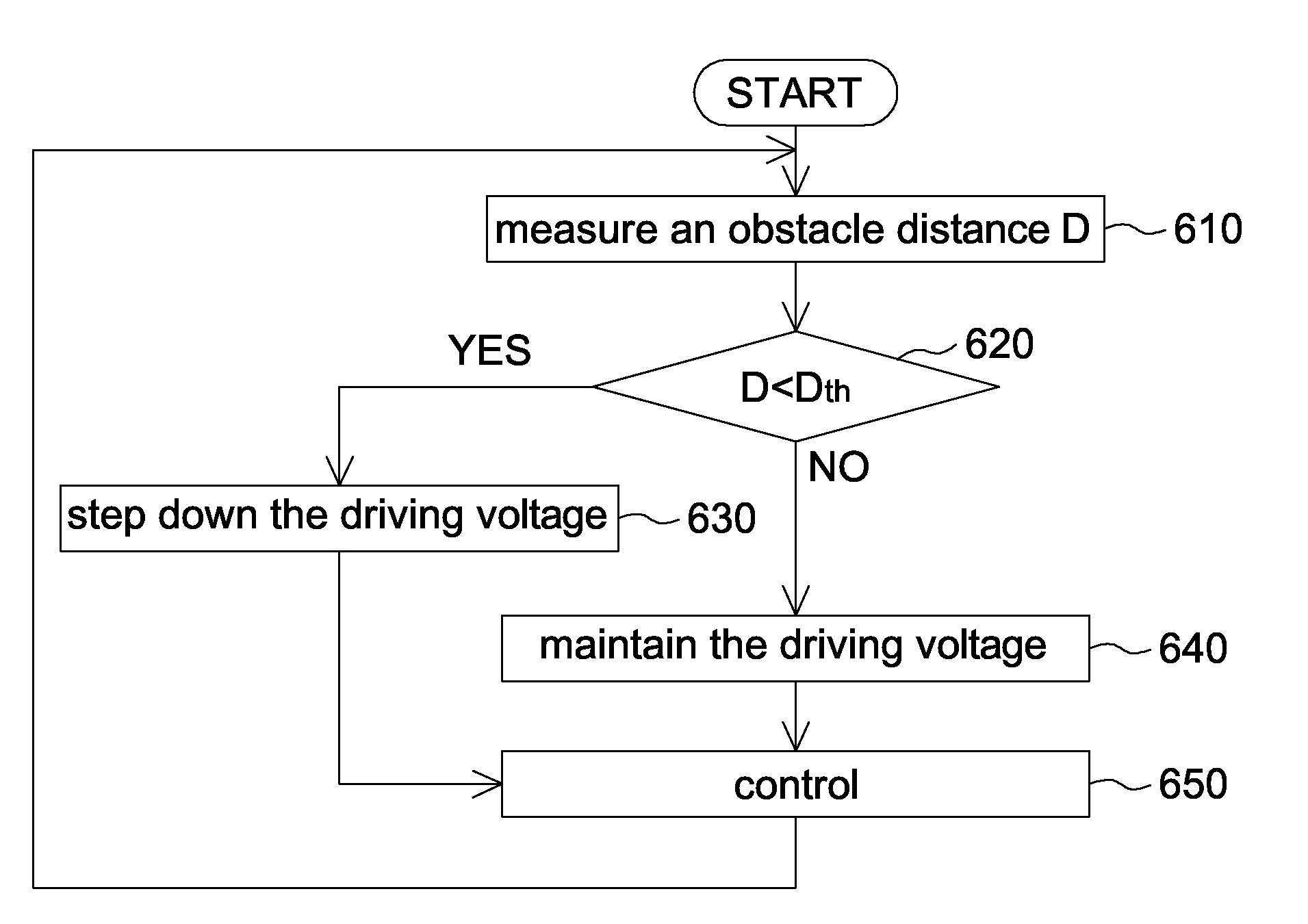
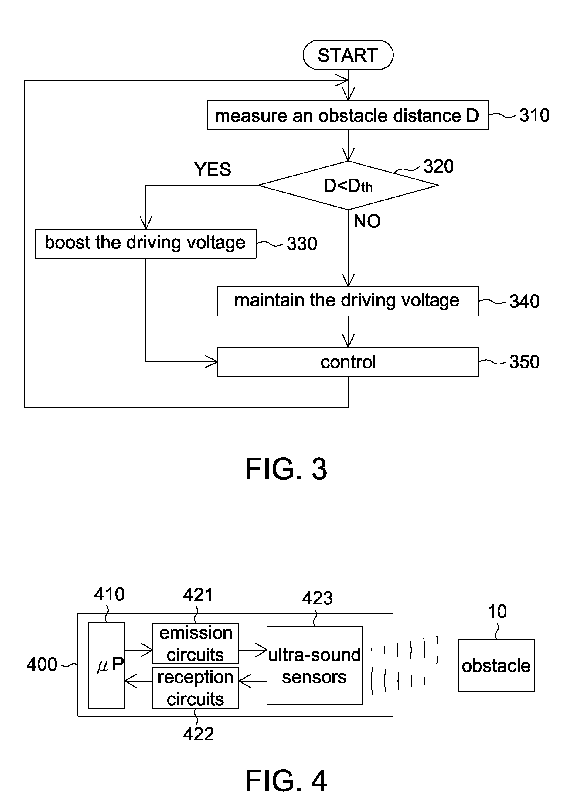
[0032]In the second embodiment of the invention, when it is detected that the obstacle distance is too short, the driving voltage of the ultra-sound sensor will be decreased to improve (i.e. shorten) the shortest detectable distance. The second embodiment of the invention is also adapted to a single ultra-sound sensor.

[0033]FIG. 4 shows a functional diagram of an electronic device according to the second embodiment of the invention. As indicated in FIG. 4, the electronic device 400 comprises a micro-processor 410, an emission circuit 421, a reception circuit 422 and an ultra-sound sensor 423. The functions of these elements are similar to the elements of FIG. 1, and are not repeated here.

[0034]FIG. 5 shows a timing diagram according to the second embodiment of the invention. In FIG. 5, μP denotes the voltage pulse signal emitted from the micro-processor, and S denotes the ultra-sound signal received / emitted by the ultra-sound sensor.

[0035]As indicated in FIG. 5, the voltage pulse si...


PUM


Abstract

A controlling method for ultra-sound sensor is provided. The method includes the steps of measuring a distance of an obstacle, determining whether the distance is smaller than a distance threshold, and adjusting a driving voltage if the distance is smaller than the distance threshold.

Description

[0001]This application claims the benefit of People's Republic of China application Serial No. 200910226445.0, filed Nov. 20, 2009, the subject matter of which is incorporated herein by reference.TECHNICAL FIELD[0002]The invention relates in general to a controlling method for ultra-sound sensor.BACKGROUND[0003]The ultra-sound sensor measures physical parameters such as location, speed and distance by emitting and receiving an ultra-sound wave. In an ordinary electronic device using an ultra-sound sensor, a micro-processor generates a driving voltage / current signal according to the frequency and magnitude of the to-be-emitted ultra-sound wave for driving the ultra-sound emitter to emit an ultra-sound wave. Then, the ultra-sound receiver receives the reflected ultra-sound wave and the micro-processor further converts the received ultra-sound wave into a voltage / current signal. Normally, the ultra-sound sensor has both functions of receiving and emitting ultra-sound waves.[0004]In som...

Claims


Application Information

Patent Timeline
Patent Type & Authority Applications(United States)
IPC IPC(8): G01S15/00
CPCG01S7/52004G01S15/04G01S7/524
Inventor HU, CHAO-WENLEE, YI-CHUNG
Owner LITE ON TECH CORP
Why Eureka
Try Eureka