Header compression scheme

a header and compression scheme technology, applied in the field of header compression scheme, can solve the problems of increasing bandwidth inefficiency, less efficient use of bandwidth, and inefficient carrying of ethern

Inactive Publication Date: 2011-05-26
BRITISH TELECOMM PLC
View PDF4 Cites 55 Cited by
  • Summary
  • Abstract
  • Description
  • Claims
  • Application Information

AI Technical Summary

Benefits of technology

[0010]Embodiments of the present invention seek to obviate and / or mitigate the above problems associated with conventional compression schemes for layer 2 communication protocols which require traffic units having a compressed state (for example, the traffic units comprising one or more compression keys along with data which has been compressed) to be distinguished by each node in the network from other traffic units comprising non-compressed traffic and / or other traffic units including other compression keys within their payload areas.

Problems solved by technology

The relatively large size of the Ethernet frame header compared to rival technologies means that bandwidth is used less efficiently when Ethernet carrier services are provided compared to Multi-Protocol Label Switching (MPLS) for short length client payloads.
As the size of the Ethernet header is larger than such small payloads they are generally, using current methods, not efficiently carried by Ethernet as a result.
The problem of bandwidth inefficiency is increased when the client traffic comprises Ethernet frames which each carry a small payload and which then need to utilize one or more Ethernet carrier networks.
However, these operate on timescales which are not suitable for adaptation to Ethernet traffic due to the very high speed communications links that Ethernet can utilize now that Terabit communication speeds are available.
This increases the delay caused by the compression scheme as each time the compressed traffic is received by another layer 3 node, it must be decompressed unless that node is able to determine all necessary routing information.
However, making the compression key detectable within the carrier network imposes an inherent security risk as this provides a potential means of identifying the traffic flow within the carrier network.

Method used


Image

  • Header compression scheme
  • Header compression scheme
  • Header compression scheme

Examples


Embodiment Construction

[0160]Embodiments of the invention will now be described. Those of ordinary skill in the art will be aware that the description of the invention has been simplified for clarity. Where features are apparent and already known to those of ordinary skill in the art as essential for the implementation of the invention these may be omitted from the description for brevity. The description may also omit to mention alternative features which are functionally equivalent to the features recited herein where these are well known in the art.

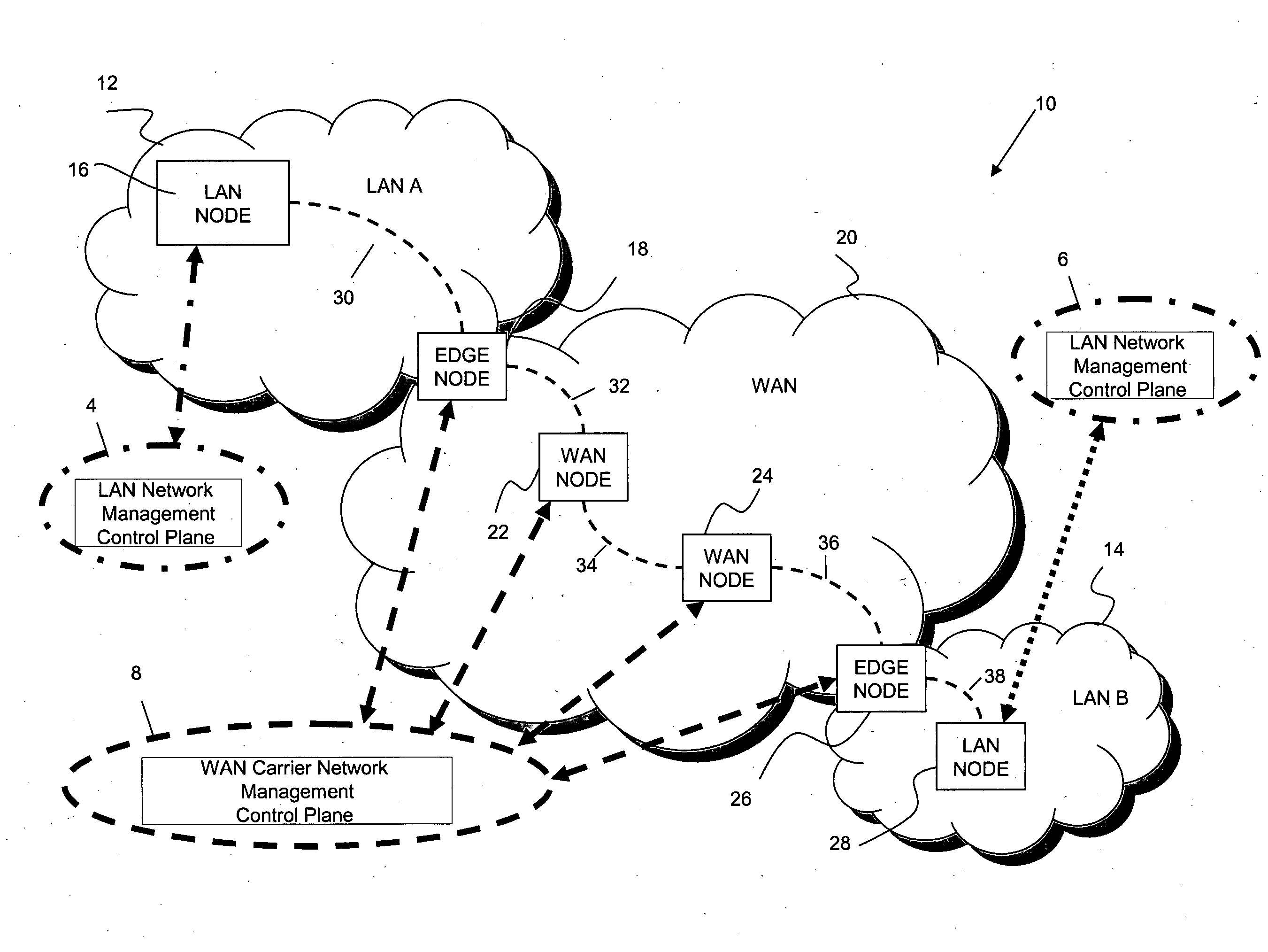
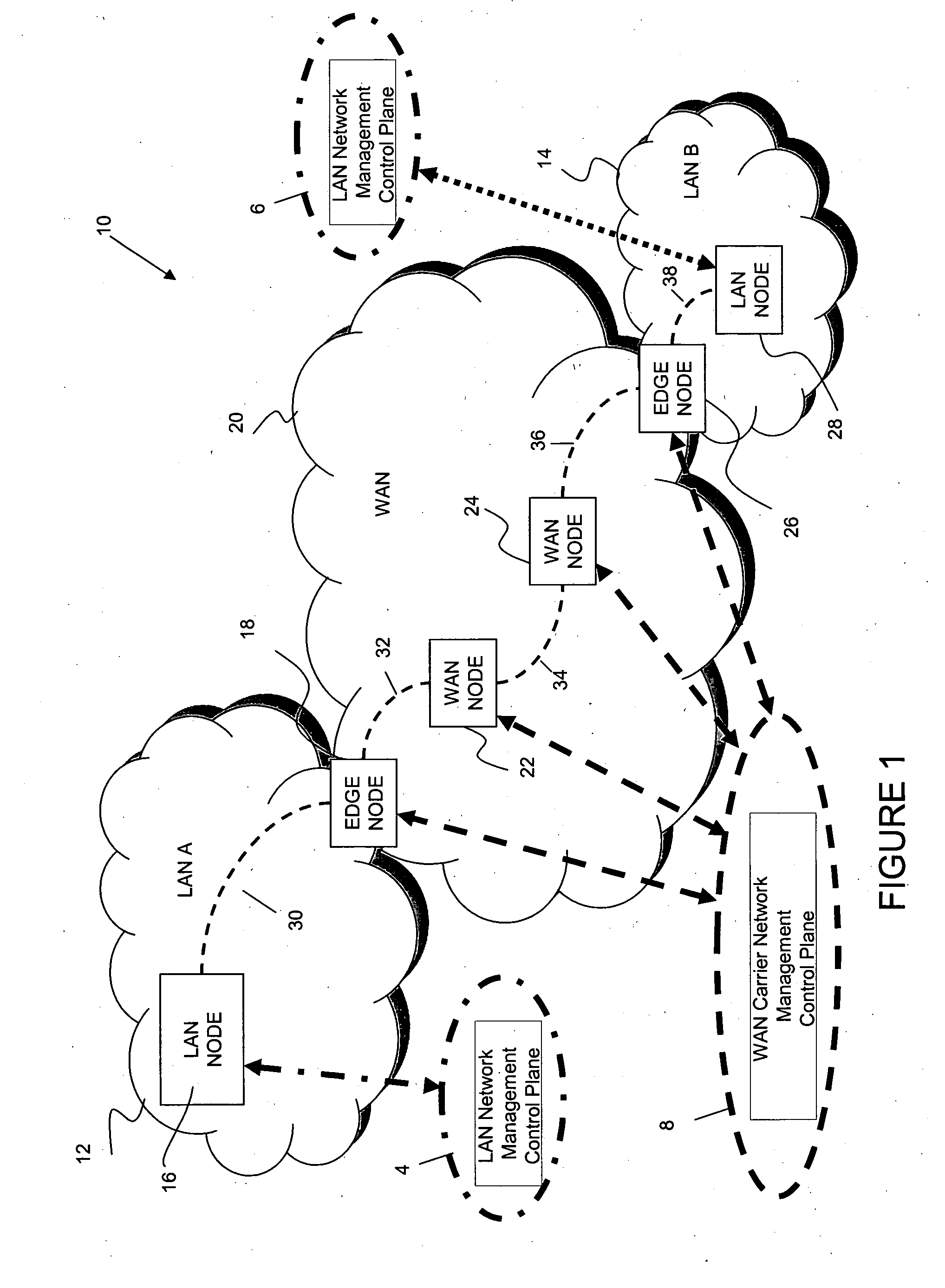
[0161]A communications system 10 according to an embodiment of the invention is shown in FIG. 1 as comprising a first network 12 (shown as LAN A, a second network 20 (shown as WAN) and a third network 14 (shown as LAN B). As those of ordinary skill in the art will realize, however, the geographic extent of each network can be different in other embodiments of the invention.

[0162]As shown in FIG. 1, LANs A and B provide a carrier service for client traffic, a...


PUM


Abstract

A method of reducing the bandwidth required to send traffic comprising a payload and a header originating in a first communications network over another communications network. The traffic is characterized by having header information from which a path from its source to destination can be predetermined, the method comprising: determining redundant header information which is not used for forwarding the traffic in the other network; replacing at least part or all of the redundant header information with compression information having a smaller bandwidth than the replaced header information; appending header information to the traffic to enable forwarding along the path in the other network to an egress node; at the egress node, processing the traffic to remove the appended header information and restore the replaced header information by removing the compression information and using the compression information to perform a look-up operation which retrieves the replaced redundant header information from a data store, wherein the same compression information is used to replace the same redundant header information for all the traffic having the same predetermined path; compression information comprising a dummy header data structure which conforms to a communications protocol arranged to be identifiable by traffic type in a carrier frame.

Description

CROSS-REFERENCE TO RELATED APPLICATIONS[0001]This application is a U.S. national stage application of International Application No. PCT / GB2009 / 001864, filed Jul. 29, 2009, which designated the U.S. and claims the benefit of European Patent Application No. 08252592.4 filed Jul. 30, 2008 and Great Britain Patent Application No. 0813920.6 filed Jul. 30, 2008, all of which are incorporated herein by reference in their entireties.TECHNICAL FIELD[0002]The present invention relates to a header compression scheme, in particular but not exclusively to a header compression scheme which improves the bandwidth efficiency of carrier Ethernet communication protocols.BACKGROUND ART[0003]Ethernet was originally devised as a local area network (LAN) communications protocol which operates in a connection-less “packet” or “frame” based communications mode. Ethernet-derived protocols having connection-oriented characteristics have been recently developed. Connection-oriented Ethernet protocols send Eth...

Claims


Application Information

Patent Timeline
Patent Type & Authority Applications(United States)
IPC IPC(8): H04L29/06
CPCH04L69/22H04L69/04
Inventor KANG, JUSTINMCGUIRE, ALAN
Owner BRITISH TELECOMM PLC
Why Eureka
Try Eureka