Low power, high resolution timing generator for ultra-wide bandwidth communication systems

a technology of ultra-wide bandwidth and timing generator, which is applied in the field of low power, high-resolution timing generator for ultra-wide bandwidth communication systems, can solve the problems of difficult to achieve, complicated cancellation of such errors over temperature, and delay in device error correction across a range of about 300 picoseconds, so as to reduce power, parts count and cost, the effect of high linearity and dynamic rang

Inactive Publication Date: 2011-05-26
NORTH STAR INNOVATIONS
View PDF26 Cites 12 Cited by
  • Summary
  • Abstract
  • Description
  • Claims
  • Application Information

AI Technical Summary

Benefits of technology

[0016]Accordingly, an object of this invention is to provide a novel method, system and computer program product for ultra wide bandwidth communication system

Problems solved by technology

However, as presently recognized most UWB transceivers use high-speed time delay generator circuits implemented using high-speed, high-power and high-cost analog and digital devices using time domain techniques.
From FIG. 21, it is seen that such devices without error correction will delay across a range of about 300 picoseconds with errors on the order of 50 picoseconds.
Cancellation of such errors over temperature is even more complicated, since drift must be cancelled as well.
However, such a string of devices must be monotonic and repeatable to a few picoseconds, which is difficult to achieve with such an implementation.
Further, linearization of such a circuit over temperature and over a dynamic range of 105 is time consuming and costly.
A further problem with the above-noted implementations, such as the invention of Fullerton et al, is that such systems suffer from jitter in the delay time.
The problem, however, is that the threshold voltage and threshold-comparator circuits are noisy, and this noise causes the time delay to be inconsistent or, in other words, jitter.
This jitter is especially difficult to control on the coarse control devices, bec

Method used


Image

  • Low power, high resolution timing generator for ultra-wide bandwidth communication systems
  • Low power, high resolution timing generator for ultra-wide bandwidth communication systems
  • Low power, high resolution timing generator for ultra-wide bandwidth communication systems

Examples


Embodiment Construction

[0047]Referring now to the drawings, wherein like reference numerals designate identical or corresponding parts throughout the several views, and more particularly to FIGS. 1A-18 thereof, there are shown various embodiments of the present invention, as will now be described.

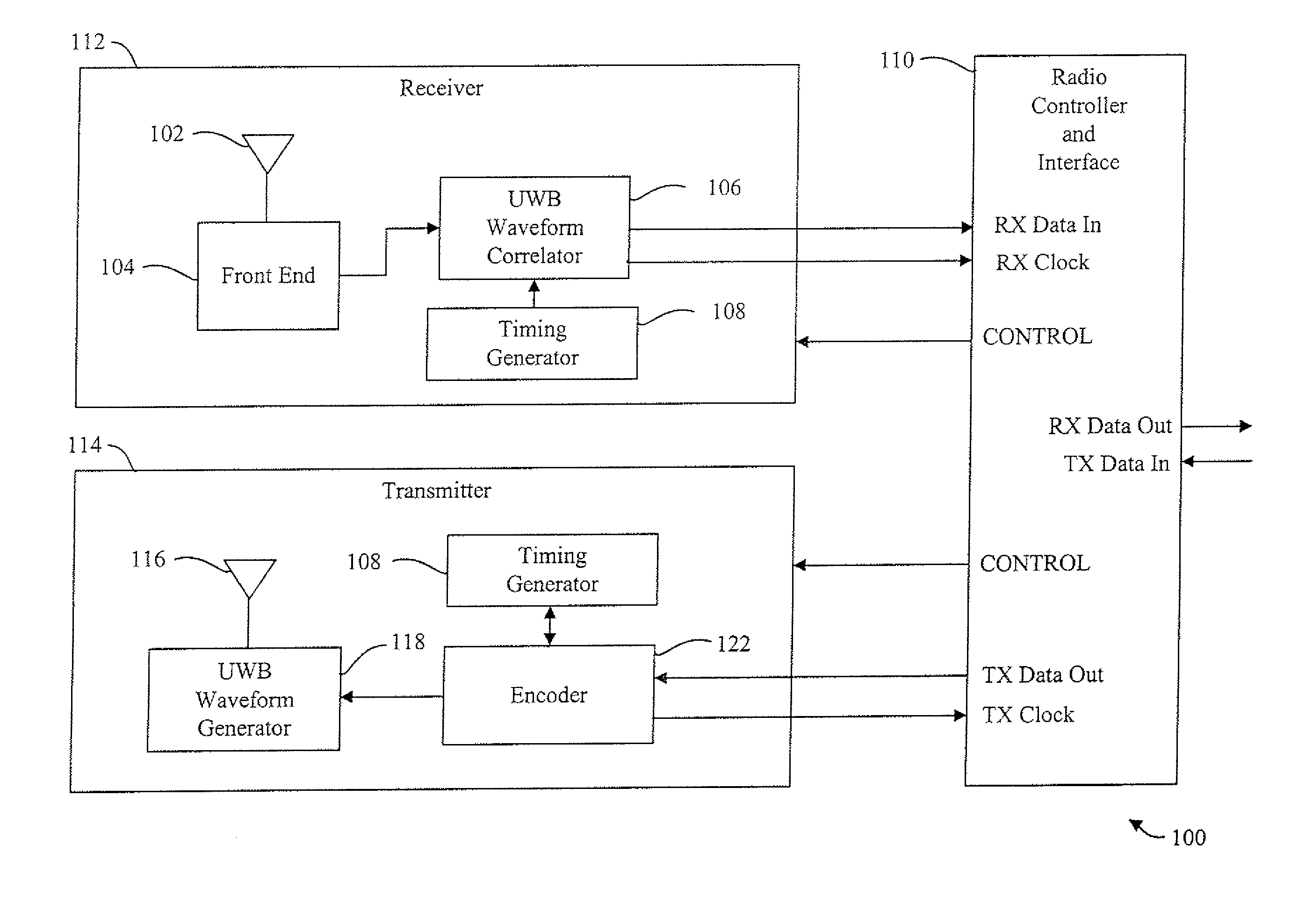
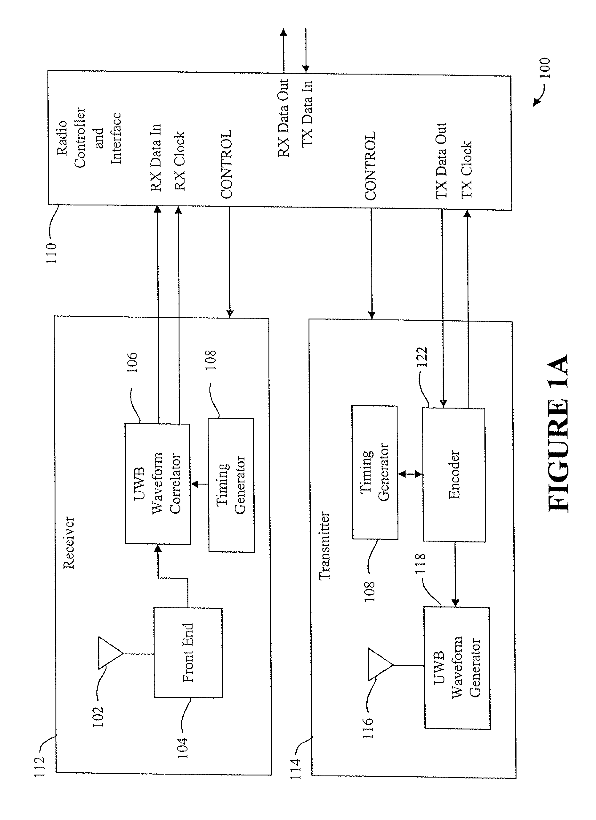
[0048]FIG. 1A is a block diagram of an ultra-wide band (UWB) transceiver 100. In FIG. 1A, the transceiver 100 includes three major components, namely, receiver 112, radio controller and interface 110, and transmitter 114. Alternatively, the system may be implemented as a separate receiver 112 and radio controller and interface 110, and a separate transmitter 114 and radio controller and interface 110. The radio controller and interface 110 serves as a media access control (MAC) interface between the UWB wireless communication functions implemented by the receiver 112 and transmitter 114 and applications that use the UWB communications channel for exchanging data with remote devices (e.g., as described with respec...


PUM


Abstract

A data communication method is provided, comprising: processing high-speed digital data for communication to produce processed data; generating short impulse wavelets; constructing a digitally modulated ultra wideband signal from the short impulse wavelets in response to bits of the processed data, wherein the digitally modulated ultra wideband signal comprises a series of the short impulse wavelets, and the value of each bit of the processed data is digitally modulated onto the shape of at least one of the short impulse wavelets of the series, to produce a series of digitally shape modulated impulse wavelets; and transmitting the digitally modulated ultra wideband signal, including the series of digitally shape modulated impulse wavelets, via an antenna.

Description

CROSS REFERENCE TO RELATED PATENT DOCUMENTS[0001]The present application is a continuation application of U.S. patent application Ser. No. 12 / 591,561, filed Nov. 24, 2009, entitled A LOW POWER, HIGH RESOLUTION TIMING GENERATOR FOR ULTRA-WIDE BANDWIDTH COMMUNICATION SYSTEMS, which is a continuation application of U.S. patent application Ser. No. 11 / 183,778, filed Jul. 19, 2005, entitled AGILE CLOCK MECHANISM AND METHOD FOR ULTRAWIDE BANDWIDTH COMMUNICATIONS SYSTEM, now issued as U.S. Pat. No. 7,643,533, which is a continuation application of U.S. patent application Ser. No. 09 / 685,199, filed Oct. 10, 2000, entitled A LOW POWER, HIGH RESOLUTION TIMING GENERATOR FOR ULTRA-WIDE BANDWIDTH COMMUNICATION SYSTEMS, now issued as U.S. Pat. No. 6,975,665.[0002]The present document contains subject matter related to that disclosed in the following commonly owned, and co-pending U.S. patent applications: Ser. No. 09 / 209,460 filed Dec. 11, 1998, entitled ULTRA WIDE BANDWIDTH SPREAD-SPECTRUM COMMU...

Claims


Application Information

Patent Timeline
IPC IPC(8): H04B1/69
CPCH04B1/7176H04B1/7174
Inventor MCCORKLE, JOHN W.
Owner NORTH STAR INNOVATIONS
Why Eureka
Try Eureka