High-Bandwidth Multimode Optical Fiber with Reduced Cladding Effect

a multi-mode, optical fiber technology, applied in the field of fiber optic transmission, can solve the problems of reducing the actual profile of the fiber, widening the resulting light pulse, and increasing the risk of the pulse being superimposed onto the trailing puls

Active Publication Date: 2011-05-26
DRAKA COMTEQ BV
View PDF98 Cites 69 Cited by
  • Summary
  • Abstract
  • Description
  • Claims
  • Application Information

AI Technical Summary

Problems solved by technology

Constraints in the manufacture of the optical fiber, however, may result in a slightly different actual profile.
This delay causes a broadening of the resulting light pulse.
Broadening of the light pulse increases the risk of the pulse being superimposed onto a trailing pulse and reduces the bandwidth (i.e., data rate) supported by the optical fiber.
In such applications, the optical fibers may be subjected to accidental or otherwise unintended bending, which can modify the mode power distribution and the bandwidth of the optical fiber.
Nevertheless, the position and the depth of the trench can significantly affect the optical fiber's bandwidth.
Nevertheless, the disclosed optical fiber exhibits higher bending losses than desired and a relatively low bandwidth.
Nevertheless, the disclosed optical fiber exhibits higher bending losses than desired.

Method used


Image

  • High-Bandwidth Multimode Optical Fiber with Reduced Cladding Effect
  • High-Bandwidth Multimode Optical Fiber with Reduced Cladding Effect
  • High-Bandwidth Multimode Optical Fiber with Reduced Cladding Effect

Examples


Embodiment Construction

The present invention embraces a multimode optical fiber that achieves reduced bending losses and a high bandwidth with a reduced cladding effect for high-data rate applications.

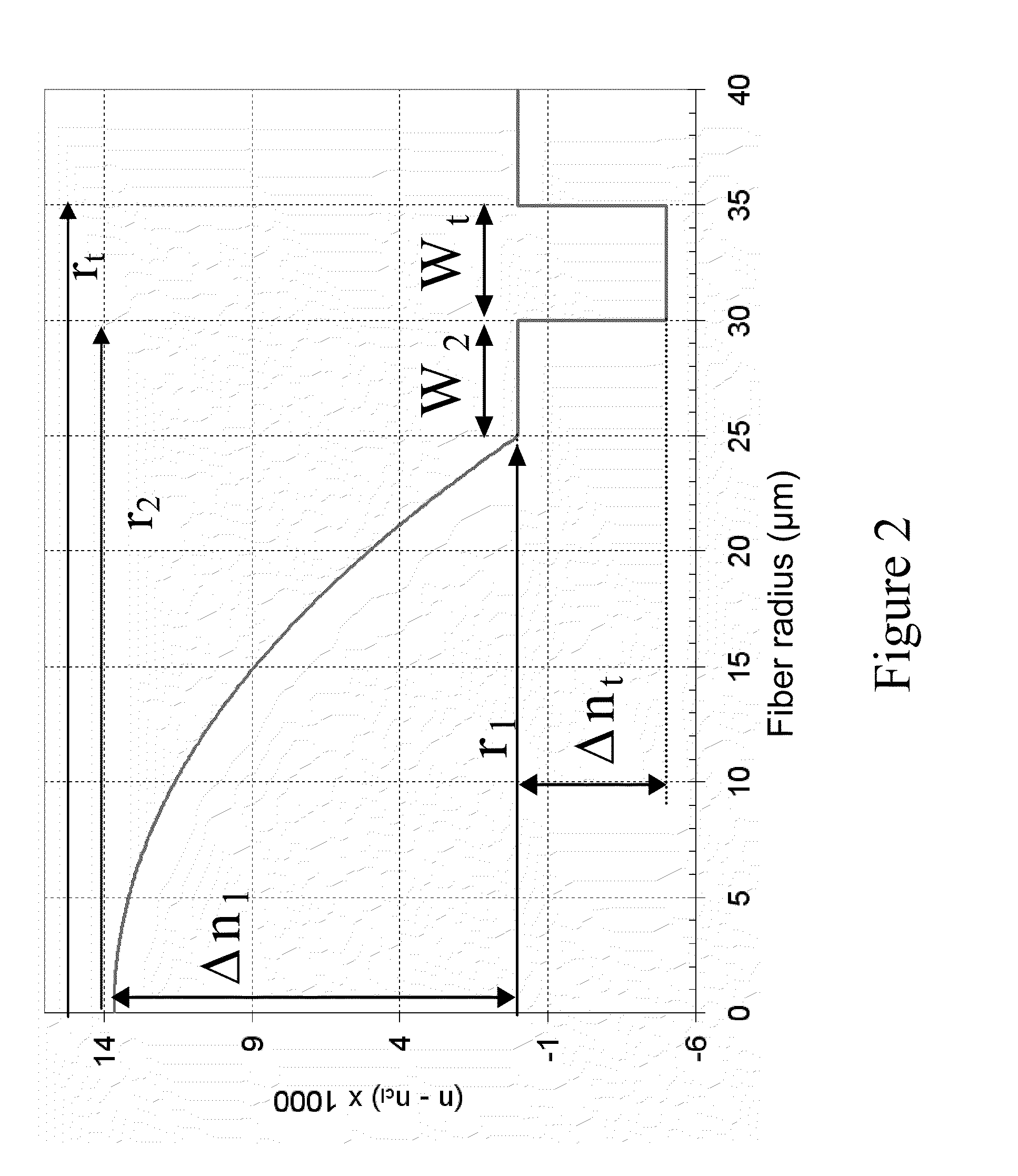
FIG. 2 depicts the refractive index profile of an exemplary optical fiber in accordance with the present invention. The optical fiber includes a central core having an outer radius r1 and an alpha refractive index profile (i.e., an alpha-index profile) with respect to an outer cladding (e.g., an outer optical cladding) surrounding the central core. Typically, the core has a radius r1 of about 25 microns. The refractive index difference between the central core and the outer cladding typically has a maximum value Δn1 of between about 11×10−3 and 16×10−3 (e.g., between about 12×10−3 and 15×10−3). The central core typically has an alpha profile with an alpha parameter of between about 1.9 and 2.1. In a particular embodiment, the central core has an alpha profile with an alpha parameter of between about 2.04 and...


PUM


Abstract

The present invention embraces an optical fiber that includes a central core having an alpha refractive index profile with respect to an outer cladding. The optical fiber also includes an inner cladding, a depressed trench, and an outer cladding. The optical fiber achieves reduced bending losses and a high bandwidth with a reduced cladding effect for high-data-rate applications.

Description

FIELD OF THE INVENTIONThe present invention relates to the field of fiber optic transmission, and, more specifically, to a multimode optical fiber having reduced bending losses and a high bandwidth for high data rate applications.BACKGROUNDAn optical fiber (i.e., a glass fiber typically surrounded by one or more coating layers) conventionally includes an optical fiber core, which transmits and / or amplifies an optical signal, and an optical cladding, which confines the optical signal within the core. Accordingly, the refractive index of the core nc is typically greater than the refractive index of the optical cladding ng (i.e., nc>ng).For optical fibers, the refractive index profile is generally classified according to the graphical appearance of the function that associates the refractive index with the radius of the optical fiber. Conventionally, the distance r to the center of the optical fiber is shown on the x-axis, and the difference between the refractive index (at radius r...

Claims


Application Information

Patent Timeline
Patent Type & Authority Applications(United States)
IPC IPC(8): G02B6/028
CPCG02B6/0365G02B6/0288
Inventor MOLIN, DENISSILLARD, PIERRE
Owner DRAKA COMTEQ BV
Why Eureka
Try Eureka