
Localized over-molding die structure

a technology of overmolding and die structure, which is applied in the direction of dough shaping, applications, and other domestic objects, can solve the problems of limiting the injection pressure for the second molding, the degree of freedom in a design becomes worse, and the overflow occurs still, so as to improve the degree of freedom, improve the quality of the vehicle appearance, and increase the yield of the product in the manufacturing process

Active Publication Date: 2011-05-26
HYUNDAI MOTOR CO LTD +2
View PDF4 Cites 3 Cited by
  • Summary
  • Abstract
  • Description
  • Claims
  • Application Information

AI Technical Summary

Benefits of technology

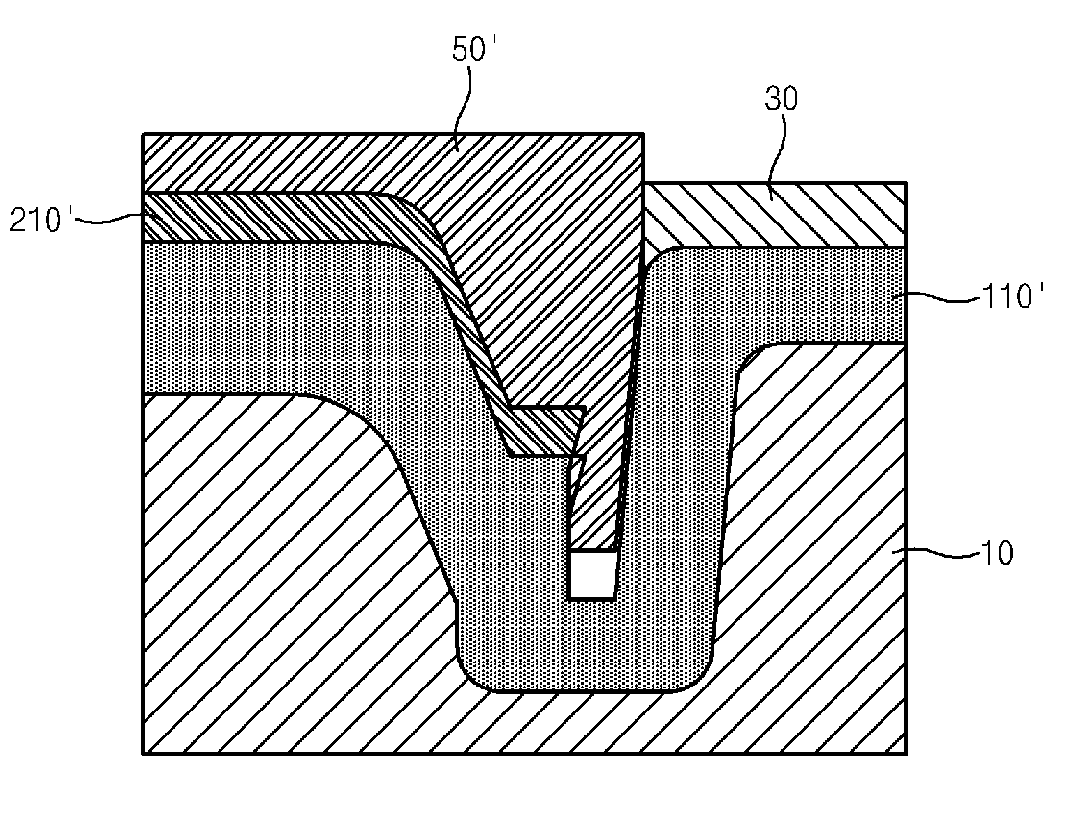
[0024]Various aspects of the present invention are directed to provide a localized over-molding die structure, wherein, by forming an undercut at the side on a step part of a slide die, when the slide die for the second injection is receded, an adhesion is applied by the interference between the first injection material and the slide die so that a forced sealing area may be formed, and accordingly, it is possible to prevent from an overflow at the localized boundary of two materials.
[0028]According to the localized over-molding die structure of the present invention, it is possible to overcome fundamentally the overflow at the localized boundary of two materials, and to stabilize injection conditions for filling up the second injection material.
[0029]By improving a degree of freedom which relates to a design and a performance such as the width and thickness of the second injection part and the like, a localized over-molding process of the present invention is also applicable to built-in parts of a vehicle in which the width of the second injection part is excessive, and accordingly, the quality of the vehicle appearance may be improved, and a yield of the products in the manufacturing process may be increased in order to decrease a manufacturing cost of the vehicle.

Problems solved by technology

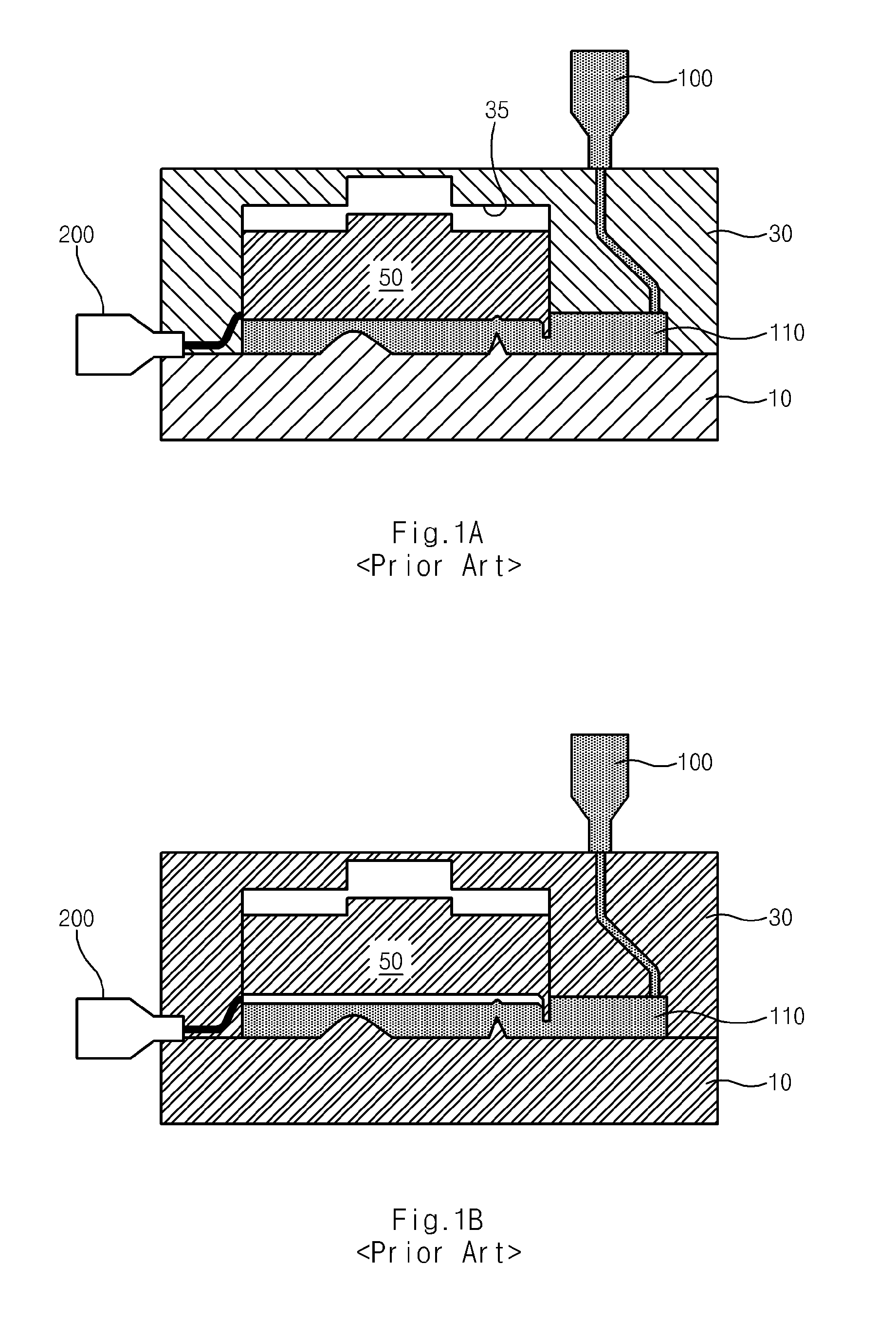
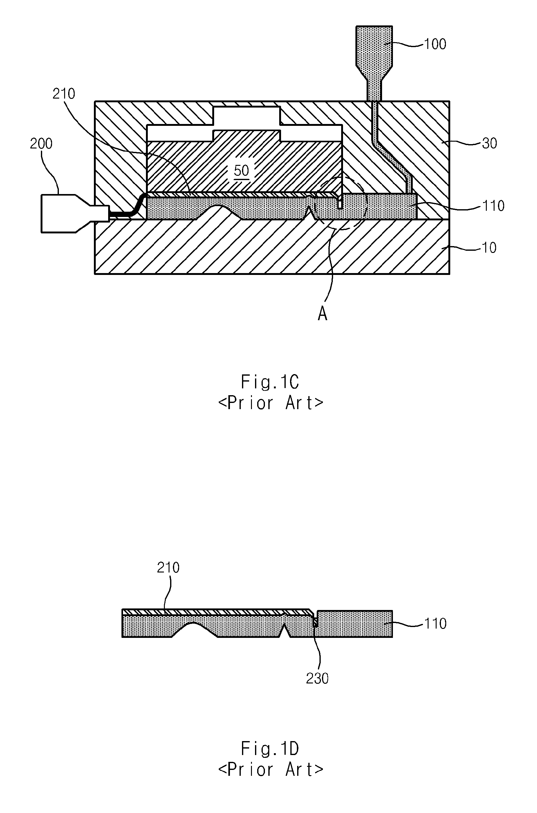
In order to overcome a problem that an overflow occurs in the material boundary with an excessive pressure, a simple groove was formed in the prior art, but, in case of this, when the width of the second injection part becomes large, the overflow occurred still, and there was a limit to improve the injection pressure for the second molding.
That is, since there was a limit to improve the injection pressure in a prior section of the material boundary, there are restricted in the width and the thickness of the second injection part, and accordingly, there was a problem that a degree of freedom in a design becomes worse.
According to the localized over-molding die structure of the prior art, the overflow may inevitably occur at the localized boundary of two materials by the above-described reasons, and accordingly, the problems may occur that a yield of the products in the manufacturing process is depreciated and the quality of the vehicle appearance is deteriorated.

Method used


Image

  • Localized over-molding die structure
  • Localized over-molding die structure
  • Localized over-molding die structure

Examples


Embodiment Construction

[0040]Reference will now be made in detail to various embodiments of the present invention(s), examples of which are illustrated in the accompanying drawings and described below. While the invention(s) will be described in conjunction with exemplary embodiments, it will be understood that present description is not intended to limit the invention(s) to those exemplary embodiments. On the contrary, the invention(s) is / are intended to cover not only the exemplary embodiments, but also various alternatives, modifications, equivalents and other embodiments, which may be included within the spirit and scope of the invention as defined by the appended claims.

[0041]Now, a localized over-molding die structure according to an exemplary embodiment of the present invention will be explained in detail on the basis of the attaching drawings.

[0042]FIG. 4 is a section view illustrating a localized over-molding die structure according to an exemplary embodiment of the present invention, and FIGS. 5...


PUM

PropertyMeasurementUnit
lengthaaaaaaaaaa
lengthaaaaaaaaaa
coloraaaaaaaaaa

Abstract

A localized over-molding die structure may include a core die, a cavity die having an inner space therein and placed onto an upper surface of the core die, and a slide die including a step portion on a lower surface thereof and slidably engaged with the cavity die in the inner space thereof to move upward and downward, wherein, the step portion includes an undercut formed at a lateral side thereof such that when at least two materials are successively injected into the cavity die, a corresponding part to the undercut is formed to at least one of the at least two materials.

Description

CROSS-REFERENCE TO RELATED APPLICATION[0001]The present application claims priority to Korean Patent Application Number 10-2009-0112543, filed on Nov. 20, 2009, the entire contents of which is incorporated herein for all purposes by this reference.BACKGROUND OF THE INVENTION[0002]1. Field of the Invention[0003]The present invention relates to a localized over-molding die structure, and more particularly, to a localized over-molding die structure, wherein it is possible to prevent from an existing circumstance (hereinafter, it is referred to an ‘overflow’) that an injection resin flows over at the material boundary when a localized over-molding process proceeds[0004]2. Description of Prior Art[0005]In general, a localized over-molding means a mold for embodying the tone of color, the quality of the material, the sense of touch or the like, by injecting each of two materials in only a mold in a localized area.[0006]When the localized over-molding is performed, the width of the second ...

Claims


Application Information

Patent Timeline
Patent Type & Authority Applications(United States)
IPC IPC(8): B29C45/44
CPCB29C2045/1687B29C45/1635Y10S425/058B29C45/16B29C45/44
Inventor KONG, BYUNG SEOKPARK, JIN-WAN
Owner HYUNDAI MOTOR CO LTD
Learn More