Separation device

Inactive Publication Date: 2011-05-26
GE HEALTHCARE BIO SCI CORP
View PDF12 Cites 17 Cited by
  • Summary
  • Abstract
  • Description
  • Claims
  • Application Information

AI Technical Summary

Benefits of technology

[0006]One object of the invention is to provide a separation device that is easy to use, including easy sample ap

Problems solved by technology

This is a tricky process since only MNCs are wanted.
A problem with this method is as desc

Method used


Image

  • Separation device
  • Separation device
  • Separation device

Examples


first embodiment

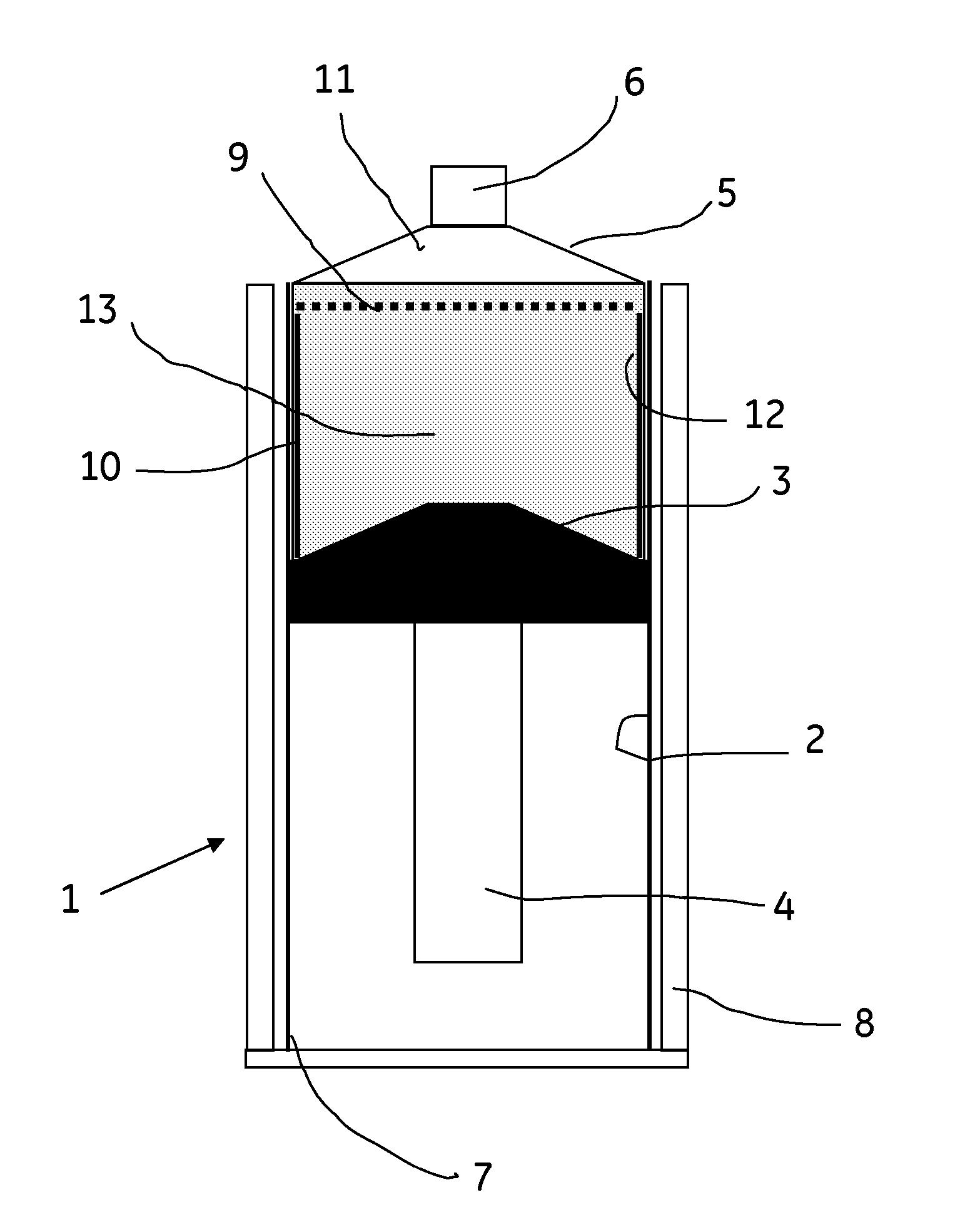
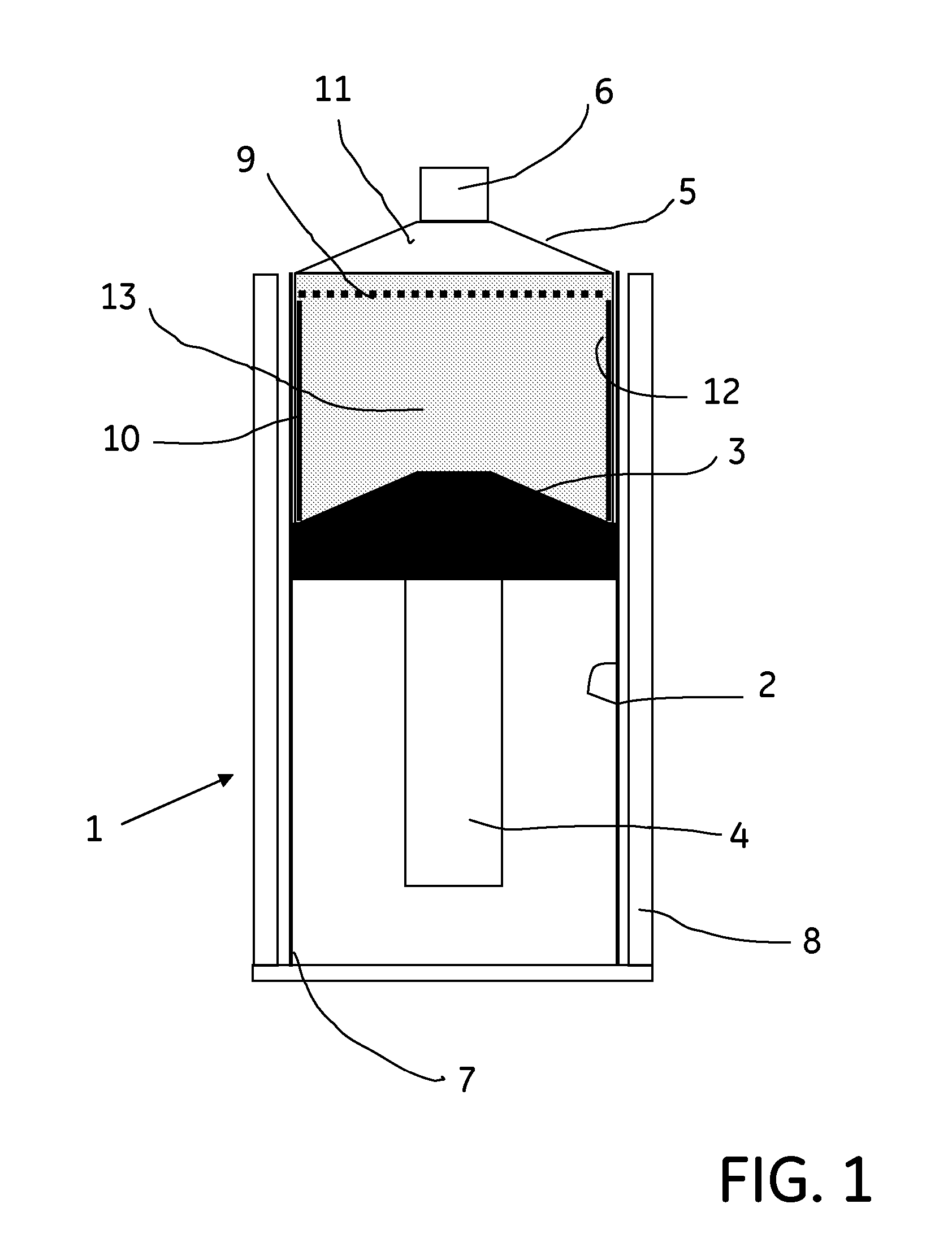
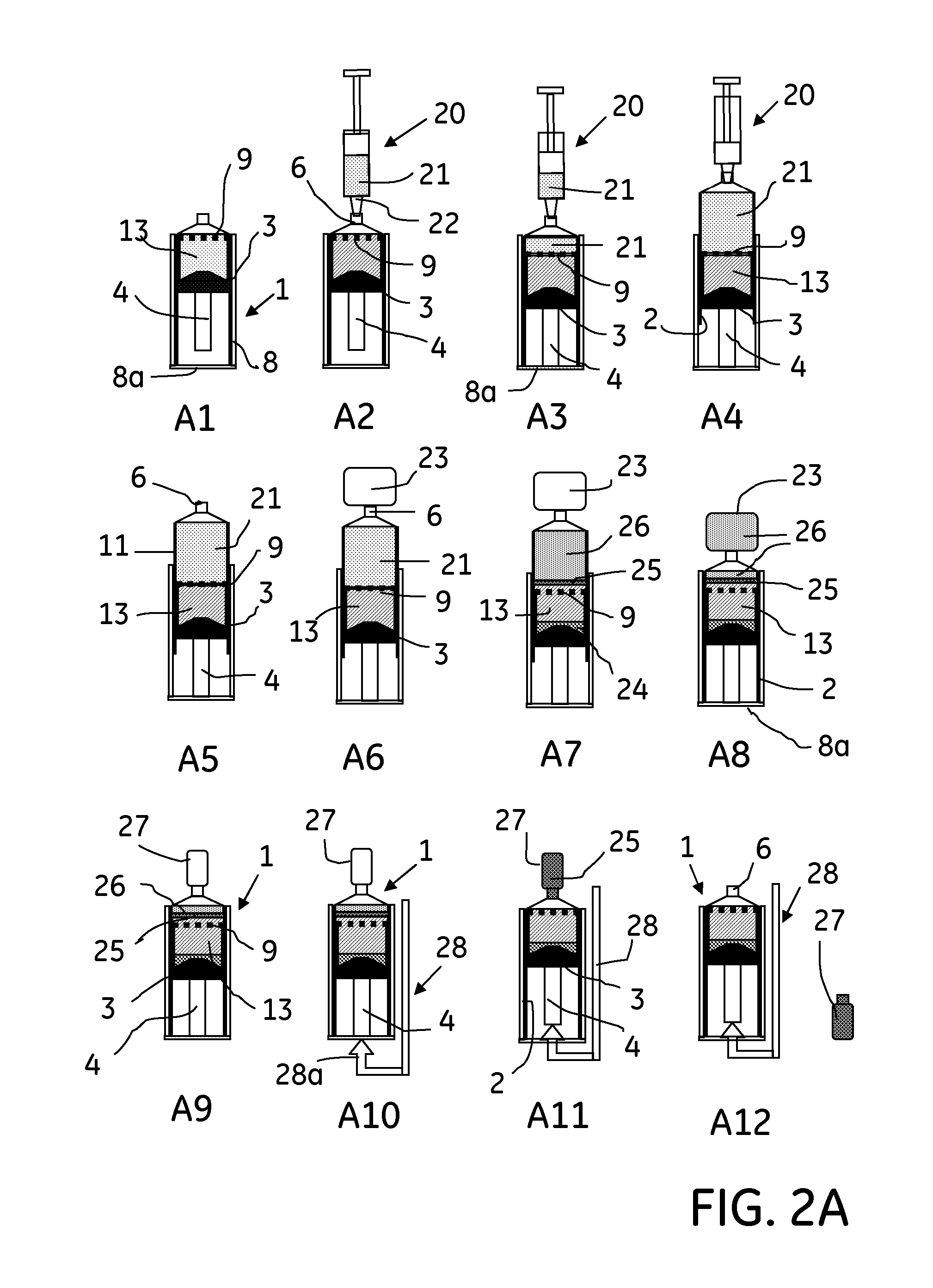
[0040]An embodiment of the syringe device of the present invention is illustrated in FIGS. 1 and 2A, 2B. With specific reference to FIG. 1, the syringe device, generally designated by reference numeral 1, includes a syringe cylinder 2 in which a plunger including a piston plug 3 with a piston rod 4 is slideably mounted. The syringe cylinder 2 has a tapering top end 5 (here a frustrated cone) with a sample inlet / outlet 6, and an open bottom end 7 (“top” and “bottom” referring to the position of the syringe device 1 on the drawing). The syringe cylinder 2 is slideably mounted in a supporting cylinder or bucket 8. A partition member 9 in the form of a filter or grid, for example, in the following for simplicity referred to as filter 9, is rigidly attached to the piston plug 3 spaced thereto, e.g. by a cylindrical member 10. In the Figure, the filter 9 is shown to be at its top position in the syringe cylinder 2 adjacent to the cone-shaped top end 5, and with the bottom end of the pisto...

second embodiment

Step Density Gradient Separation

[0063]Another embodiment of the syringe device of the present invention is illustrated in FIGS. 3 to 6. With specific reference to FIG. 3, the syringe device, generally designated by the reference numeral 31, similarly to the syringe device in FIGS. 1 and 2A, 2B comprises a syringe cylinder 32 in which a plunger or piston including a piston plug 33 and a piston rod 34 is slidingly mounted. The top end 35 of the cylinder 32 tapers to a sample inlet / outlet 36, whereas the bottom end 37 of the cylinder is open. In the illustrated case, the inlet / outlet 36 is capped by a stopper 38. A partition member 39 in the form of a filter or grid, for example, in the following for simplicity referred to as filter 39, is attached to the piston plug 33 and divides the volume enclosed between the piston plug 33 and the inlet / outlet 36 into a sample compartment 41 above the filter 39 and a compartment 42 below the filter 39 for containing a density gradient medium 43.

[0...


PUM

PropertyMeasurementUnit
Densityaaaaaaaaaa
Speedaaaaaaaaaa
Affinityaaaaaaaaaa

Abstract

A separation device for separating a wanted end product from a liquid sample comprises a container (2) having a first end (5) and a second end (7), the first end having a central orifice (6), a plunger (3) slideably disposed in the container (2) to define a variable liquid receiving chamber between the plunger (3) and the orifice (6), and a permeable partition member (9) mounted to the plunger (3) in a spaced relationship thereto to define a compartment (12) between the partition member (9) and the plunger (3) for receiving liquid density gradient medium (13), wherein liquid may be drawn into the container (2) and expelled therefrom, respectively, through the orifice (6) by movement of the plunger (3) relative to the container (2). A method for separating a wanted end product from a liquid sample is also disclosed.

Description

CROSS-REFERENCE TO RELATED APPLICATIONS[0001]This application is a filing under 35 U.S.C. §371 and claims priority to international patent application number PCT / SE2009 / 050909 filed Jul. 20, 2009, published on Feb. 4, 2010 as WO 2010 / 014033, which claims priority to application number 0801746-9 filed in Sweden on Jul. 31, 2008.FIELD OF THE INVENTION[0002]The present invention relates to a separation device adapted for separation of a wanted end product from a sample by centrifugation, and to a method for separation of a wanted end product from a sample using the separation device.BACKGROUND OF THE INVENTION[0003]The separation of cell containing samples, for example blood, into different fractions by using centrifugation and a density gradient medium has been practised for some time. The principle used is to provide for example a blood sample together with a density gradient medium in a tube and then put the tube into a centrifuge. The density gradient medium is suitably chosen such...

Claims


Application Information

Patent Timeline
IPC IPC(8): C12N5/071B01D35/28
CPCB01L3/0217G01N33/491B01L2400/0478B01L3/5021
Inventor FROMAN, GUNNAROSTLIN, HENRIK
Owner GE HEALTHCARE BIO SCI CORP
Why Eureka
Try Eureka