Respiratory therapy system including a nasal cannula assembly

a technology of respiratory therapy and cannula, which is applied in the field of respiratory assistance equipment, can solve the problems of patient discomfort, irritation and inflammation, wearer frequently encountered discomfort, etc., and achieve the effects of accurate prediction of breathing characteristics, easy exhaustion of excess respiratory gas, and high pressure drop

Active Publication Date: 2011-05-26
SALTER LABS LLC
View PDF56 Cites 97 Cited by
  • Summary
  • Abstract
  • Description
  • Claims
  • Application Information

AI Technical Summary

Benefits of technology

[0010]The nasal cannula is a unitary member desirably made of a highly flexible or pliable material. The cannula is molded so as to define a narrow central member and a pair of flexible supply arms integrally formed along opposite edges of the central member that are connectable to pair of auxiliary respiratory gas supply lines. The inner ends of the supply arms define a pair of spaced-apart hollow tubular extensions or prongs projecting in a slightly curved configuration from the central member. The tubular extensions are inserted into the nostrils of the wearer and their slightly curved configuration permits a positive guiding of the respiratory gas supply along the natural contours of the nasal passages into the pharynx.
[0031]As used in this patent application and in the appended claims, the term “trough” means an opening, passageway, indentation or some other exterior surface irregularity such as, for example, a channel, a groove, a slot, a flute, or the like which facilitates leakage, in either flow direction, between the inwardly facing nasal cavity skin of a patient and the exterior surface of the head of the cannula.

Problems solved by technology

Even though many of these cannulas were made of soft, flexible plastic, the wearer frequently encountered discomfort because a cannula is usually worn for a prolonged period of time.
This results in continued contact of the cannula with the wearer's facial tissues, especially at the philtrum and around the unprotected nasal-labial area, thereby causing irritation and inflammation.
Under these circumstances, a patient usually begins to experience discomfort in a relatively short period of time even if the cannula itself and the auxiliary oxygen supply tubes connected thereto are designed to deliver relatively low flows of oxygen, i.e., they not particularly robust, stiff or heavy in weight.
However, the harness members of these devices also typically span all or most of the length of a patent's upper lip whereby the devices, even for light-duty gas delivery applications, produce the same patient discomfort problems as the cannula devices of the first group.
However, none of the nasal cannulas disclosed in that publication describe a device that would be comfortable to a patient under the high flow conditions a patient would experience under positive airway pressure therapy, e.g., continuous positive airway pressure (CPAP) or bilevel positive airway pressure (BiPAP), that is often prescribed to patients suffering from Obstructive Sleep Apnea (OSA).
Tubes of this caliber, when inserted short distances into the nostrils (as they must be so as not to harm the internal nasal tissues), would be quite obtrusive, stiff and uncomfortable to the user, especially when in elastic contact with the user's septum.
Such discomfort would, in turn, detrimentally impact the patient's compliance with his or her prescribed positive airway pressure regime and, therefore, reduce the overall effectiveness of therapy.
However, the cannula devices disclosed in these documents are quite large and cumbersome.
Consequently, they too are not conducive to optimum patient therapy compliance.

Method used


Image

  • Respiratory therapy system including a nasal cannula assembly
  • Respiratory therapy system including a nasal cannula assembly
  • Respiratory therapy system including a nasal cannula assembly

Examples


Embodiment Construction

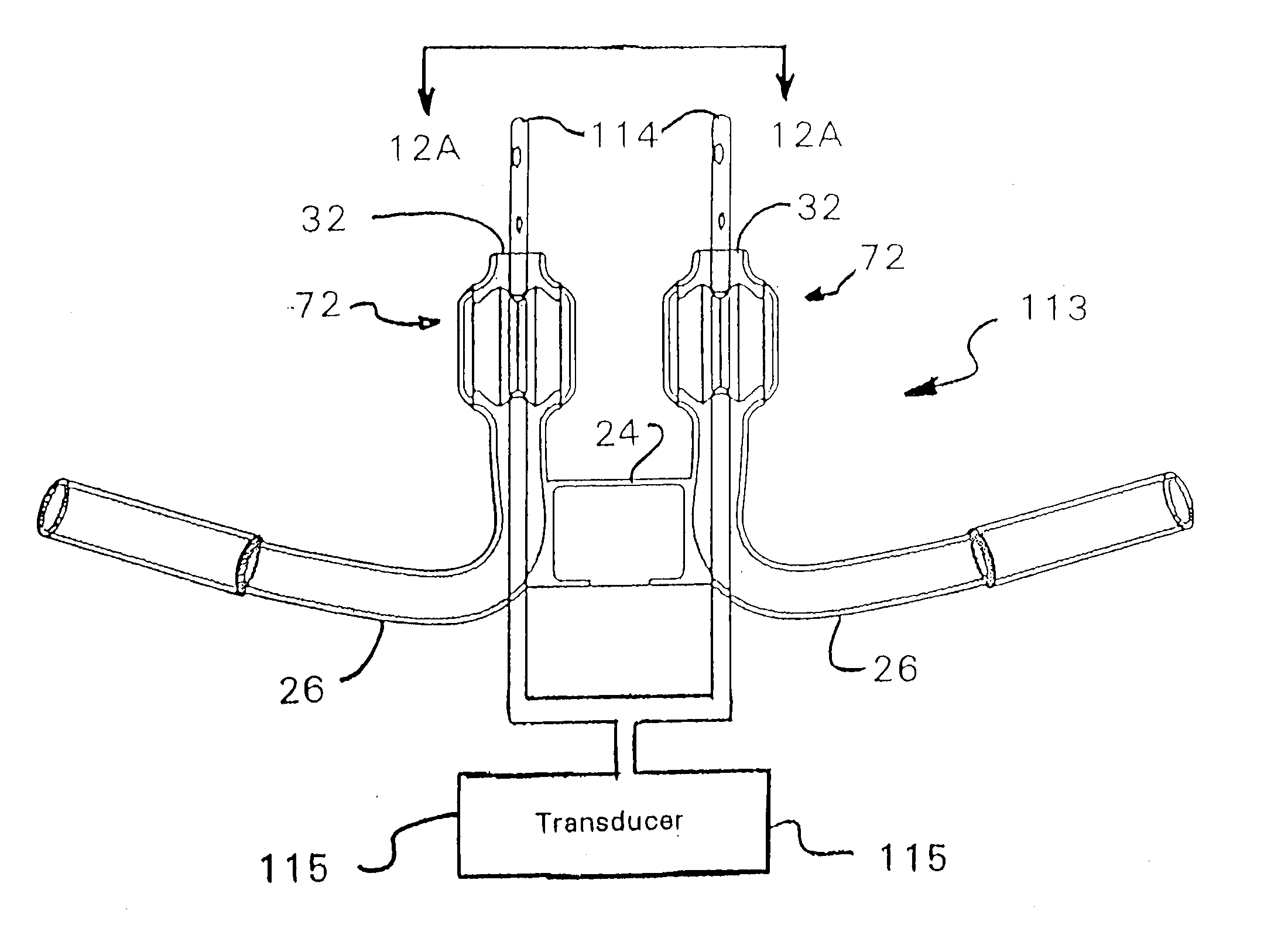
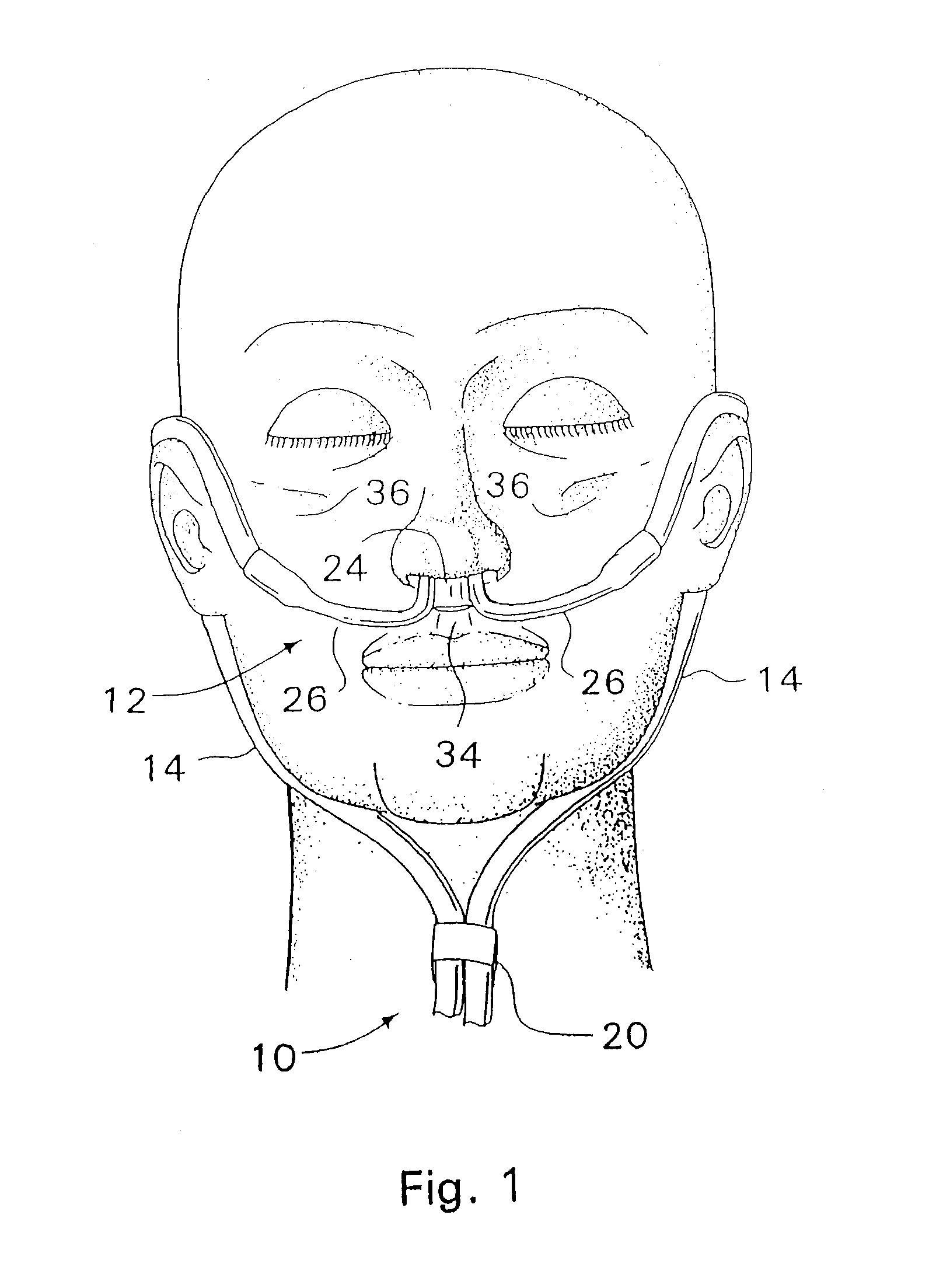
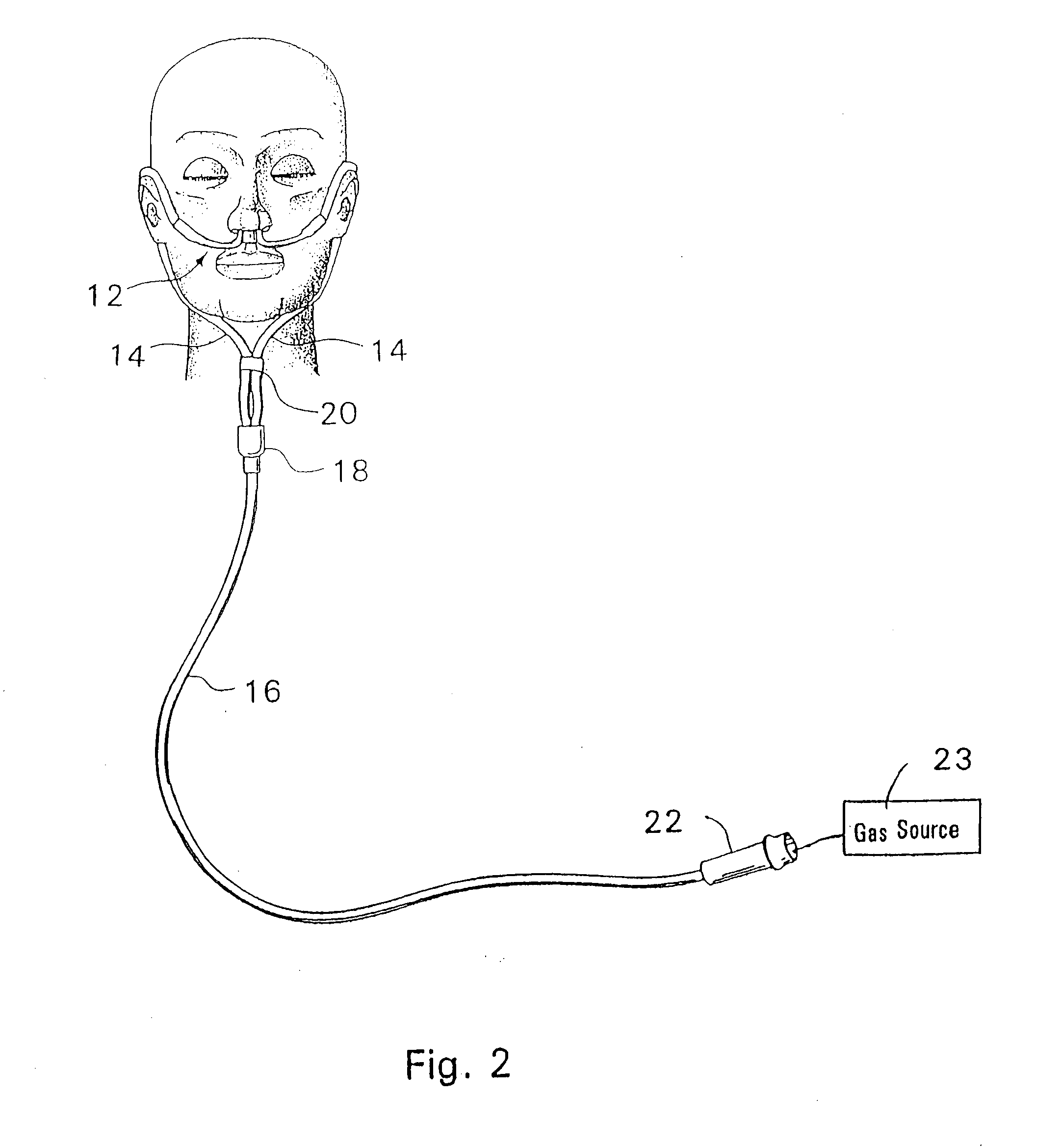
[0075]Referring to the drawings wherein like or similar references indicate like or similar elements throughout the several view, a nasal cannula assembly, according to the present invention, generally designated by reference numeral 10, is shown in FIGS. 1 and 2 in an operative position on a patient's face. The nasal cannula assembly 10 comprises a nasal cannula 12, a pair of auxiliary respiratory gas supply lines 14 connected to supply lines or arms 26 of the cannula (described below in further detail), a main respiratory gas supply line 16, a connector 18 for coupling each of the auxiliary lines 14 to the main respiratory gas supply line 16, an optional slip loop or line tightening member 20 disposed about auxiliary lines 14 for facilitating adjustment of the auxiliary lines about the patient's ears and head, and an end connector 22 for facilitating connection of a second end of the main respiratory gas supply line 16 to a pressurized respiratory or respiratory gas source 23. As ...


PUM


Abstract

A nasal cannula, for supplying a respiratory gas to a patient, comprising: a pair of spaced apart supply lines which each have a head at one end thereof with a discharge opening therein. The opposite end of each supply line is connectable to a respiratory gas source. Each head is sized to be snugly received and retained within one of the nasal cavities of the patient while forming a sufficient leakage passage, between a portion of inwardly facing nasal cavity skin of a patient and a portion of an exterior surface of the head, to facilitate exhausting of any excess respiratory gas supplied to the patient through the leakage passage and also facilitate inhalation of any room air required in excess of the respiratory gas to be supplied to the patient. The invention also relates to a respiratory therapy system incorporating the nasal cannula, a method of treating a patient with sleep disorder by using the nasal cannula, a diagnostic tool for measuring nasal cavity pressure of a patient, and a method of using the diagnostic tool for measuring nasal cavity pressure of a patient.

Description

FIELD OF THE INVENTION[0001]The present invention relates in general to respiratory assistance equipment and, in particular, to a respiratory therapy system including a nasal cannula assembly for use in the administration of fluids such as oxygen into the nasal passages of a patient having respiratory ailments.BACKGROUND OF THE INVENTION[0002]A variety of flexible cannulas have been produced that are positioned to contact the nasal-labial area between the patient's upper lip and nostrils. Even though many of these cannulas were made of soft, flexible plastic, the wearer frequently encountered discomfort because a cannula is usually worn for a prolonged period of time. This results in continued contact of the cannula with the wearer's facial tissues, especially at the philtrum and around the unprotected nasal-labial area, thereby causing irritation and inflammation.[0003]The structures of conventional cannula devices may be categorized into two general groups.[0004]The first group ut...

Claims


Application Information

Patent Timeline
Patent Type & Authority Applications(United States)
IPC IPC(8): A61M16/16A61M16/00A61B5/03
CPCA61M16/0051A61M16/161A61M16/16A61M2016/0039A61M2205/3372A61M2205/3382A61M2205/3386A61M2205/42A61M16/0683A61M16/0069A61M16/0672A61M16/0694A61M16/109A61M16/1095A61M16/0666A61M16/0605A61M16/0825A61M16/0833A61M16/0858A61M16/022
Inventor DAVENPORT, JAMES M.CURTI, JAMES N.SALTER, PETER W.CHUA, JAMESCRANDALL, BARRY
Owner SALTER LABS LLC
Why Eureka
Try Eureka