Tire and method of producing the same
a technology of tire and circumferential groove, which is applied in the field of tires, can solve the problems of uneven wear, shorten the product life of the tread rubber in terms of wear, and deteriorate the driving stability and riding comfort of the vehicle, and achieve the effect of relatively low noise and uneven wear
- Summary
- Abstract
- Description
- Claims
- Application Information
AI Technical Summary
Benefits of technology
Problems solved by technology
Method used
Image
Examples
example 1
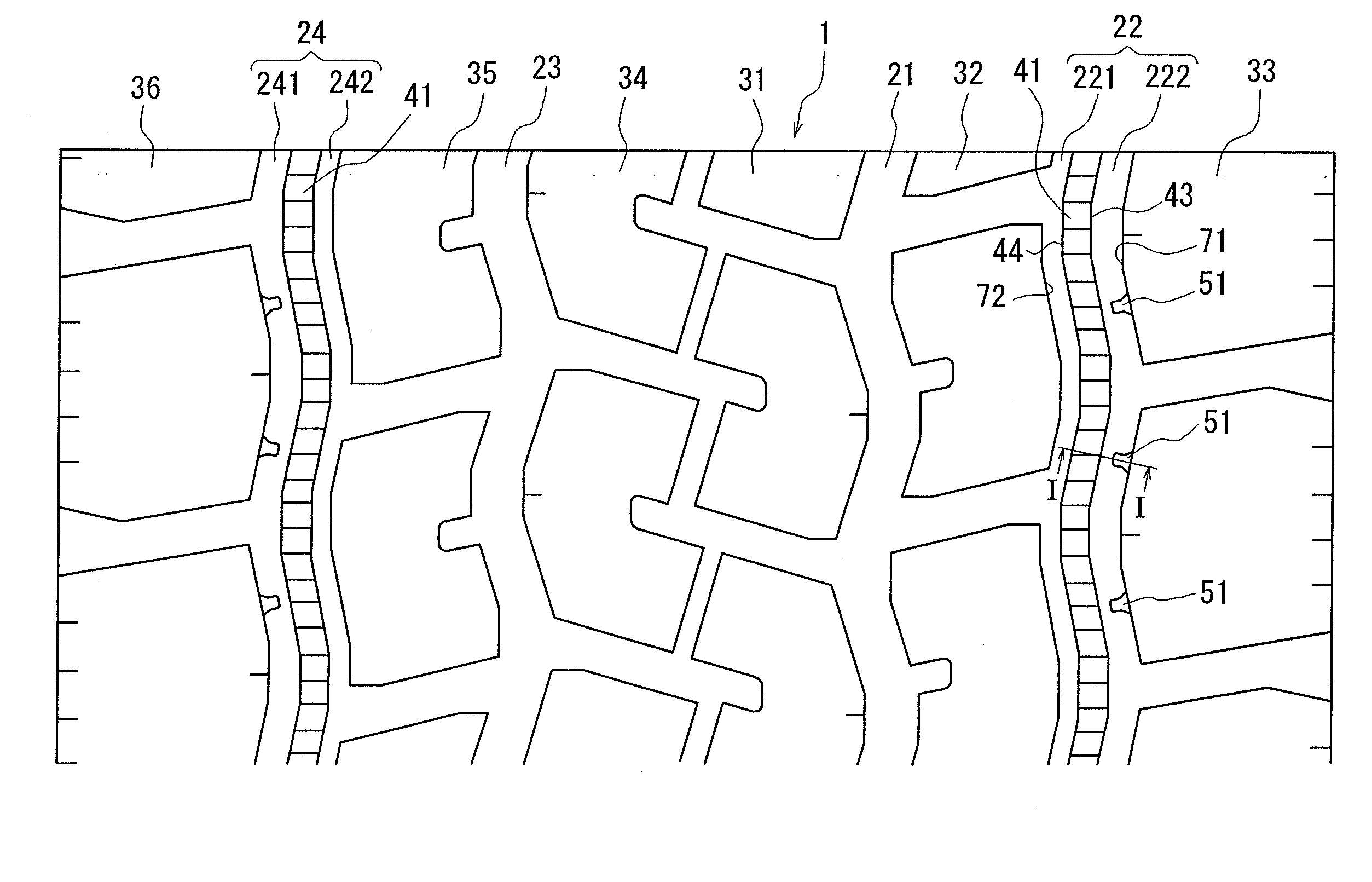
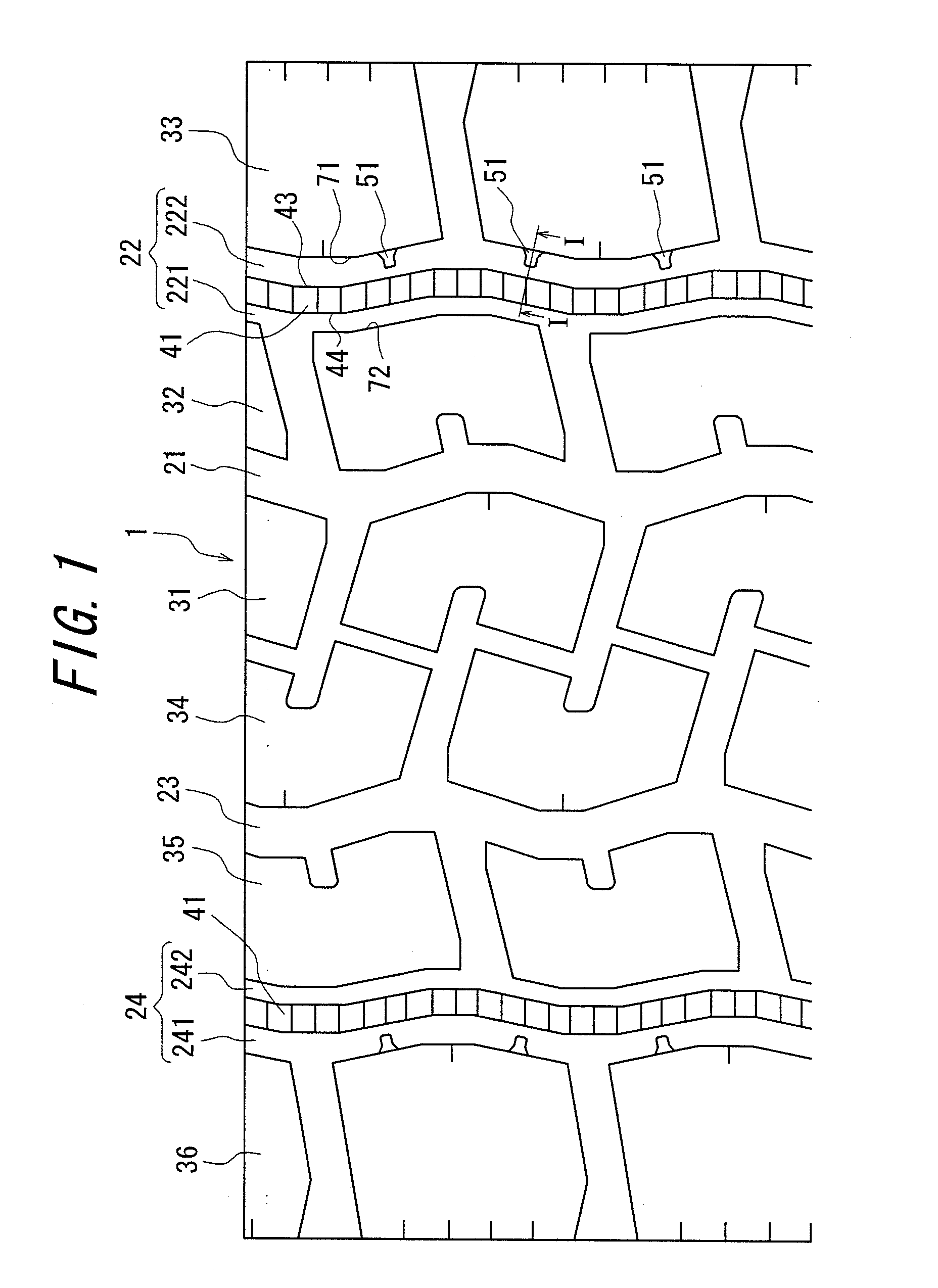
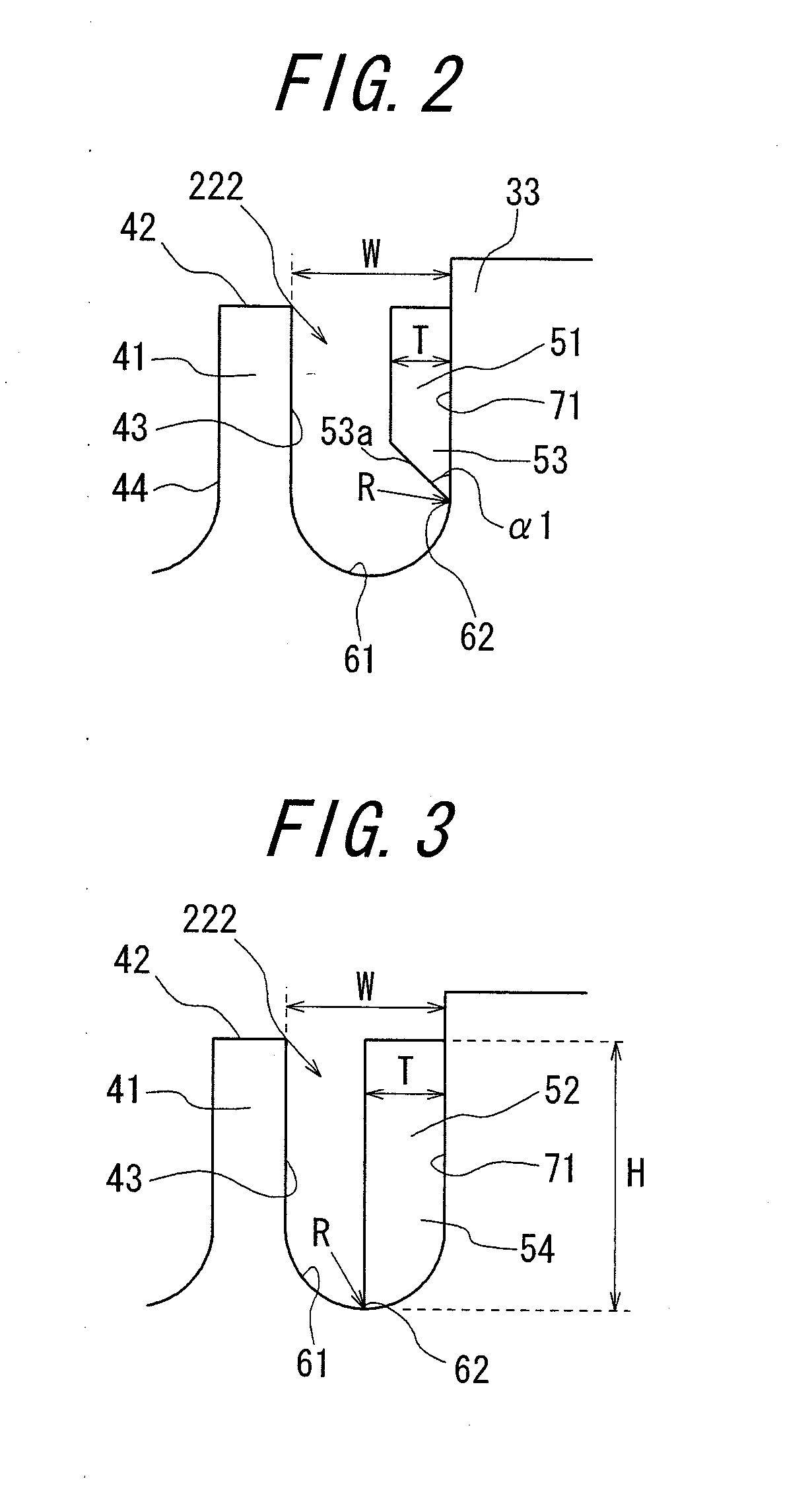
[0045]In Example 1, there was used as a sample a 15° taper radial ply tire for a truck or a bus (tire size: 11822.2 16PR, rim size: 8.25), in which: a stepped land portion is provided in the circumferential groove; the groove wall positioned on the outer side in the tire widthwise direction of the circumferential groove portion (depth: 16.7 mm, width: 5 mm, radius of curvature: 2 mm) facing the stepped land portion is provided with groove fences which are formed along the tire circumferential direction at intervals of 250 mm therebetween such that each groove fence has a shape as shown in FIG. 2 and includes a thin wall portion having depth: 2 mm, the maximum protruding width T: 3 mm and the length H in the tire radial direction: 13 mm and that an angle formed by a notched face of the thin wall portion with respect to the at least one of the wall surfaces provided with the groove fence is set at 60′; and the tire is inflated at an air pressure of 800 kPa.
example 2
[0046]In Example 2, there was used as a sample a 15° taper radial ply tire for a truck or a bus (tire size: 11822.2 16PR, rim size: 8.25), in which: a stepped land portion is provided in the circumferential groove; the groove wall positioned on the outer side in the tire widthwise direction of the circumferential groove portion (depth: 16.7 mm, width: 5 mm, radius of curvature: 2 mm) facing the stepped land portion is provided with thirty groove fences formed along the tire circumferential direction at intervals of 250 mm therebetween such that each groove fence has a shape as shown in FIG. 2 and includes a thin wall portion having depth: 2 mm, the maximum protruding width T: 3 mm and the length H in the tire radial direction: 13 mm; and the tire is inflated at an air pressure of 800 kPa.
[0047]There were prepared six sample types in which the angle formed by a notched face of the thin wall portion with respect to the groove wall provided with the groove fence is 30°, 50°, 60°, 70°, ...
example 3
[0048]In Example 3, respective sample tires were prepared in a manner similar to that of Example 2, except that the groove fences are provided at a side wall of the stepped land portion (not the circumferential groove) positioned on the outer side in the tire widthwise direction.
PUM
| Property | Measurement | Unit |
|---|---|---|
| angle | aaaaa | aaaaa |
| thickness | aaaaa | aaaaa |
| thickness | aaaaa | aaaaa |
Abstract
Description
Claims
Application Information
 - R&D
- Intellectual Property
- Life Sciences
- Materials
- Tech Scout
- Unparalleled Data Quality
- Higher Quality Content
- 60% Fewer Hallucinations
Browse by: Latest US Patents, China's latest patents, Technical Efficacy Thesaurus, Application Domain, Technology Topic, Popular Technical Reports.
© 2025 PatSnap. All rights reserved.Legal|Privacy policy|Modern Slavery Act Transparency Statement|Sitemap|About US| Contact US: help@patsnap.com


