

Arm-wheel type robotic vehicle comprising suspension system
- Summary
- Abstract
- Description
- Claims
- Application Information
AI Technical Summary
Benefits of technology
Problems solved by technology
Method used
Image

Examples
Embodiment Construction
[0039]Exemplary embodiments will be described in detail below with reference to the attached drawings.
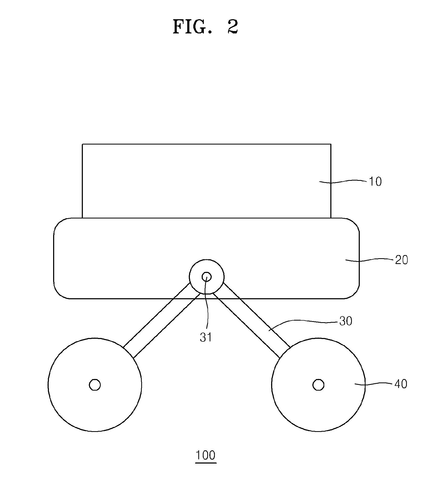
[0040]FIG. 2 is a schematic side view of a robotic vehicle employing a suspension system, according to an exemplary embodiment. The robotic vehicle is provided with a main body, an arm 30, and wheels 40. The main body may be formed of a body 20, and an assembly 10 mounted on the body 20. The body 20 is a frame that supports the assembly 10. Here, the body 20 is a portion that is horizontal overall with respect to a flat ground surface.
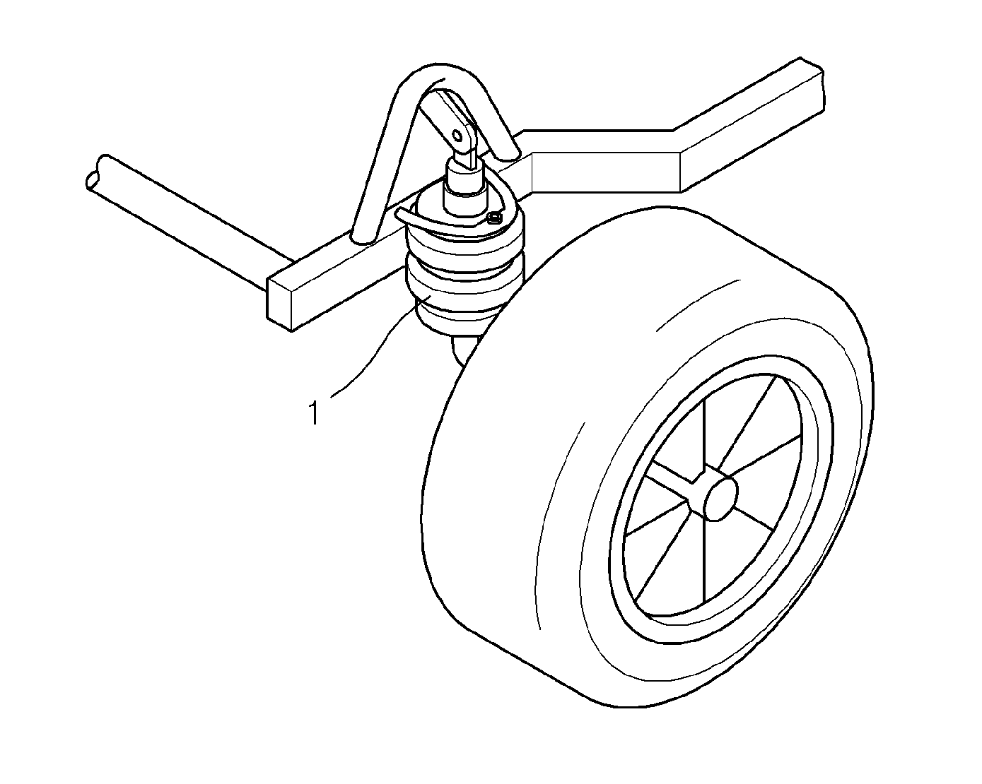
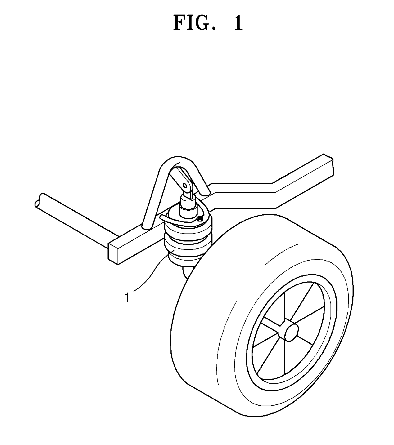
[0041]The robotic vehicle has two arms 30 at the left side and right side, respectively. Each arm 30 has a wheel 40 mounted on one end thereof. The arm 30 with the wheel 40 mounted on one end thereof is pivotally controllable. The arms 30 on one side of the robotic vehicle pivot about a common pivot axle 31. The arms (not shown) on the other side of the robotic vehicle also pivot about a common pivot axle (not shown). Here, the pivot axle 31 that is th...
PUM
 Abstract
Description
Claims
Application Information