Backlight assembly and LCD having the same

Inactive Publication Date: 2006-01-05
LG DISPLAY CO LTD
View PDF4 Cites 0 Cited by
  • Summary
  • Abstract
  • Description
  • Claims
  • Application Information

AI Technical Summary

Benefits of technology

[0019] An advantage of the present invention is to provide a backlight assembly capable of decreasing the driving voltage of the EFFLs and securing stability in a high voltage.
[0020] Additional features and advantages of the invention will be set forth in the description which follows, and in part will be apparent from the description, or may be learned by practice of the invention. The objectives and other advantages of the invention may be realized and attained by the structure particularly pointed out in the written description and claims hereof as well as the appended drawings.
[0021] To achieve these and other advantages and in accordance with the purpose of the invention, as embodied and broadly described, there is provided a backlight assembly comprising: an external electrode fluorescent lamp (EEFL) including an external electrode through which a driving voltage is applied, and a lamp for emitting light; a side support for supporting the EEFL; and a protective cap disposed above a portion of the external electrode, the portion of the external electrode being exposed out of the side support.
[0022] In another aspect of the present invention, there is provided an LCD comprising: a backlight assembly, wherein the back

Problems solved by technology

However, reducing the length of the external electrodes results in increased driving voltage for the lamp 13 Large-sized LCD panels require longer EFFLs resulting in even higher driving voltages.
Consequently, it is difficult to apply the EEFL to the LCD.
However, this approach requires that the width of the side supports or bezel be widened

Method used


Image

  • Backlight assembly and LCD having the same
  • Backlight assembly and LCD having the same
  • Backlight assembly and LCD having the same

Examples


Embodiment Construction

[0032] Reference will now be made in detail to embodiments of the present invention, examples of which are illustrated in the accompanying drawings. Wherever possible, the same reference numbers will be used throughout the drawings to refer to the same or like parts.

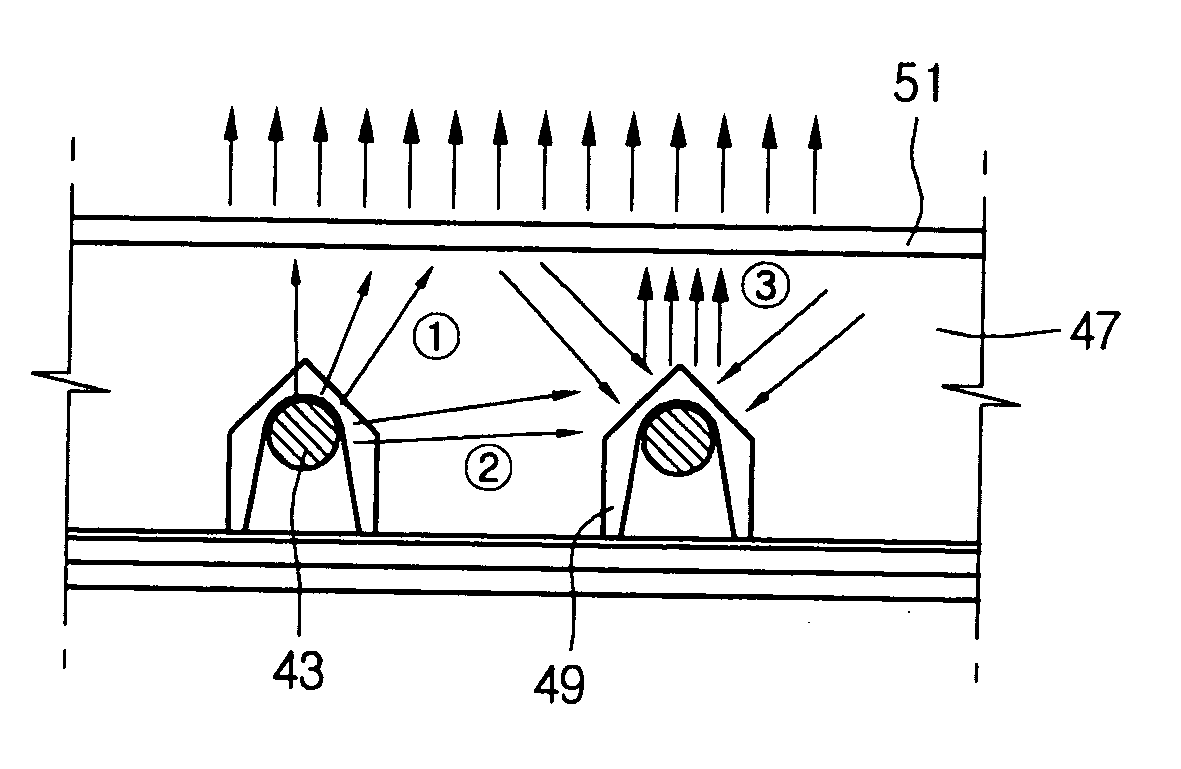
[0033] In order to solve these problems, the present invention provides a backlight assembly having a structure illustrated in FIG. 4. FIG. 4 is a perspective view of a direct type backlight assembly according to an embodiment of the present invention.

[0034] Referring to FIG. 4, the backlight assembly 41 includes a plurality of lamps 43 having external electrodes formed on each end (not shown), side supports 41 for supporting the plurality of lamps 43, and protective caps 49 disposed above the exposed above the exposed external electrodes. Although not shown, the external electrode for applying a driving voltage to the EEFLs 43 are partially exposed out of the side support 7 (toward an inner space of the backlight asse...


PUM


Abstract

A backlight assembly includes: an EEFL (external electrode fluorescent lamp) including an external electrode through which a driving voltage is applied, and a lamp for emitting light; a side support for supporting the EEFL; and a protective cap disposed above a portion of the external electrode, the portion of the external electrode being exposed out of the side support.

Description

[0001] This application claims the benefit of Korean Patent Application No. 2004-49949, filed on Jun. 30, 2004, which is hereby incorporated by reference for all purposes as if fully set forth herein. BACKGROUND OF THE INVENTION [0002] 1. Field of the Invention [0003] The present invention relates to a backlight assembly and an LCD having the same. [0004] 2. Description of the Related Art [0005] A current trend in the development of display devices is to replace the cathode ray tube (CRT) with a liquid crystal display (LCD) or a plasma display panel (PDP). The LCD has been found to have lower power consumption, slimmer profile, and lighter weight compared with the CRT. In addition, LCD devices do not generate harmful electromagnetic waves. For these reasons, LCD devices are considered the next generation in display device technology. [0006] Generally, an LCD includes a lower substrate on which thin film transistors (TFTs) are formed, an upper substrate on which color filters are for...

Claims


Application Information

Patent Timeline
IPC IPC(8): G02B6/00
CPCG02F1/133611G02F1/133604G02F1/1335
Inventor JEONG, IN SUK
Owner LG DISPLAY CO LTD
Why Eureka
Try Eureka