Material for organic electroluminescent device and organic electroluminescent device using same

Inactive Publication Date: 2018-08-16
NIPPON MICROMETAL
View PDF8 Cites 0 Cited by
  • Summary
  • Abstract
  • Description
  • Claims
  • Application Information

AI Technical Summary

Benefits of technology

[0022]The material for an organic electroluminescent device of the present invention shows an excellent electron-injecting/transporting property and an excellent hole-injecting/transporting property. In addition, the material has proper lowest singlet excitation energy and proper lowest triplet excitation energy that affect its light-emitting characteristic. Accordingly, the use of the material i

Problems solved by technology

Further, investigations have been made on using a europium complex as an attempt to

Method used


Image

  • Material for organic electroluminescent device and organic electroluminescent device using same
  • Material for organic electroluminescent device and organic electroluminescent device using same
  • Material for organic electroluminescent device and organic electroluminescent device using same

Examples


Example

Example 1

[0088]

[0089]In a stream of a nitrogen gas, dibenzothiophene (1-A) (109 mmol, 20.0 g) and dehydrated THF (100 mL) were added to a 1,000-milliliter reactor, and were stirred at 0° C. for 30 min. A 2 N solution of BuLi in hexane (60 mL, 156 mmol) was dropped to the mixture. After the completion of the dropping, the mixture was heated to reflux for 6 hr. After the resultant had been cooled to room temperature, dehydrated DMF (20 mL, 160 mmol) was dropped to the resultant, and then the mixture was stirred overnight at room temperature. The reaction mixture was poured into 6 N hydrochloric acid (500 mL), and the whole was extracted with acetic acid. The organic layer was washed with water and dried, followed by column chromatography. Thus, 8.0 g of a compound (1-B) was obtained.

[0090]In a stream of a nitrogen gas, 3-bromopropionic acid (1-C) (169 mmol, 25 g), triphenylphosphine (196 mmol, 51.42 g), and dehydrated acetonitrile (70 mL) were added to a 500-milliliter reactor. After ...

Example

Example 2

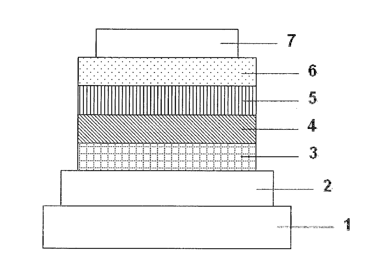
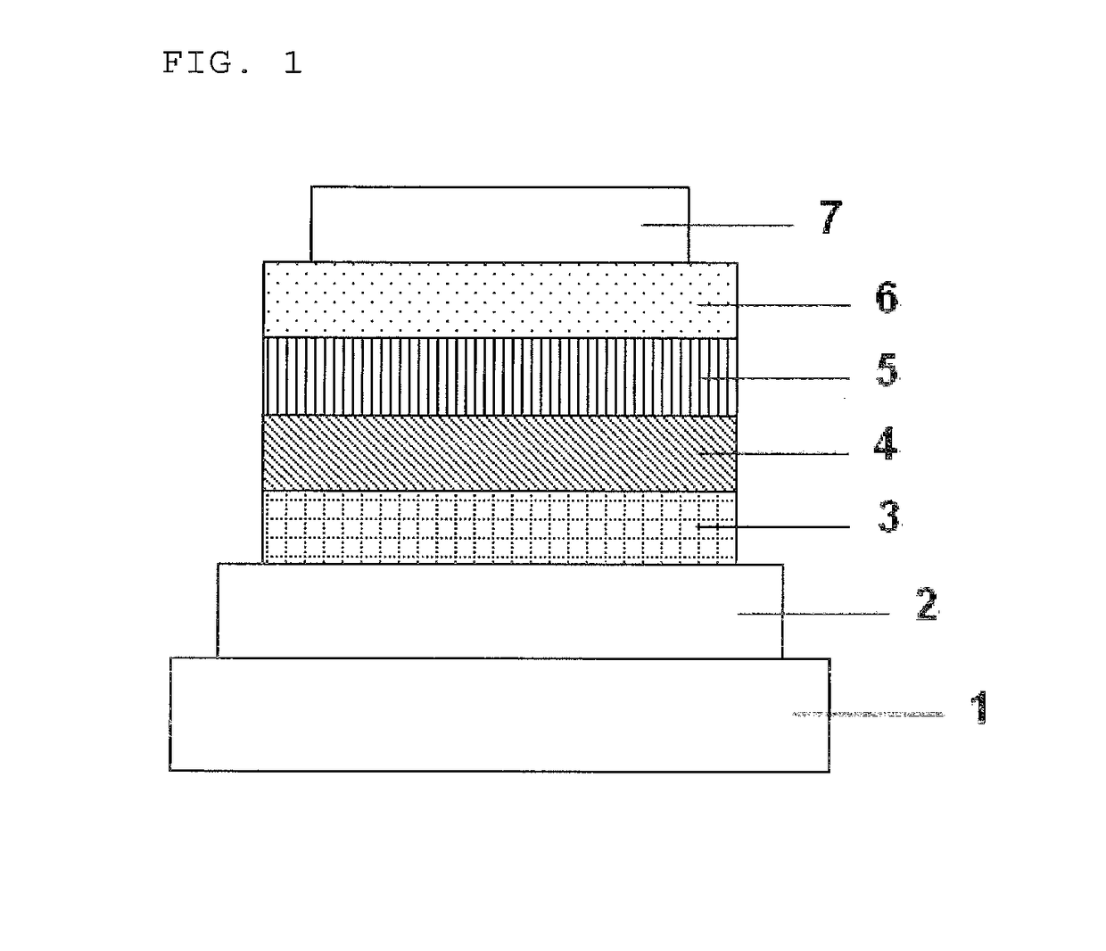
[0099]Each thin film was laminated by a vacuum deposition method at a degree of vacuum of 2.0×10⁻⁵ Pa on a glass substrate on which an anode formed of indium tin oxide (ITO) having a thickness of 150 nm had been formed. First, copper phthalocyanine (CuPC) was formed into a layer having a thickness of 20 nm to serve as a hole-injecting layer on the ITO. Next, α-NPD was formed into a layer having a thickness of 40 nm to serve as a hole-transporting layer. Next, the compound (3) serving as a host material for a light-emitting layer and Ir(ppy)3 serving as a dopant were co-deposited from different deposition sources onto the hole-transporting layer to form a light-emitting layer having a thickness of 35 nm. The concentration of Ir(ppy)3 was 7.0%. Next, Alq3 was formed into a layer having a thickness of 40 nm to serve as an electron-transporting layer. Further, lithium fluoride (LiF) was formed into a layer having a thickness of 0.5 nm to serve as an electron-injecting layer on ...

Example

Examples 3 to 7

[0101]Organic EL devices were each produced in the same manner as in Example 2 except that the compound (4), (5), (10), (13), or (18) was used as a host material for the light-emitting layer in Example 2 instead of the compound (3).


PUM


Abstract

Provided are a material for an organic electroluminescent device showing excellent electron- and hole-injecting/transporting properties, and having proper lowest singlet excitation energy and proper lowest triplet excitation energy, and an organic EL device using the material. The material for an organic electroluminescent device includes a heterocyclic compound represented by the general formula (1) where: R1 represents an aromatic hydrocarbon group having 6 to 30 carbon atoms, an aromatic heterocyclic group having 3 to 22 carbon atoms, or a linked aromatic group obtained by linking 2 to 6 aromatic rings of the aromatic groups, an alkyl group, or an alkoxy group; R2 to R5 each represent an aromatic hydrocarbon group having 6 to 30 carbon atoms, an aromatic heterocyclic group having 3 to 22 carbon atoms, the group containing only oxygen or sulfur as a heteroatom, or a linked aromatic group obtained by linking 2 to 6 aromatic rings of the aromatic groups, an alkyl group, or an alkoxy group; and a, b, c, and d each represent an integer of from 0 to 2.

Description

TECHNICAL FIELD[0001]The present invention relates to an organic electroluminescent device using a specific heterocyclic compound as a material for an organic electroluminescent device, and more specifically, to a thin film-type device that emits light by applying an electric field to a light-emitting layer containing an organic compound.BACKGROUND ART[0002]In general, an organic electroluminescent device (hereinafter referred to as organic EL device) includes a light-emitting layer and a pair of counter electrodes interposing the light-emitting layer therebetween in its simplest structure. That is, the organic EL device uses the phenomenon that, when an electric field is applied between both the electrodes, electrons are injected from a cathode and holes are injected from an anode, and each electron and each hole recombine in the light-emitting layer to emit light.[0003]In recent years, progress has been made in developing an organic EL device using an organic thin film. In order t...

Claims


Application Information

Patent Timeline
IPC IPC(8): H01L51/50H01L51/52H01L51/00
CPCH01L51/5024H01L51/5056H01L51/5072H01L51/5092H01L51/5096H01L51/5234H01L51/5206H01L51/5016H01L51/0072H01L51/0074C07D495/04H05B33/20H10K85/322H10K85/348H10K85/371H10K85/346H10K85/654H10K85/6576H10K85/6574H10K85/657H10K85/342H10K85/6572H10K50/17H10K50/15H10K50/11H10K2101/10H10K2101/20C09K11/06C09K2211/1037H10K50/00H10K50/12H10K50/16H10K50/18H10K50/81H10K50/171H10K50/828
Inventor KAI, TAKAHIROTANAKA, HIDEKIKAWADA, ATSUSHI
Owner NIPPON MICROMETAL
Why Eureka
Try Eureka