Display device

Inactive Publication Date: 2007-06-14
SAMSUNG SDI CO LTD
View PDF1 Cites 2 Cited by
  • Summary
  • Abstract
  • Description
  • Claims
  • Application Information

AI Technical Summary

Benefits of technology

[0016] The present embodiments provide a display device in which

Problems solved by technology

However, since the protective layer 24 made of MgO has a low secondary electron emission coefficient, there is a limitation in making a sufficient

Method used


Image

  • Display device
  • Display device
  • Display device

Examples


Embodiment Construction

[0044] The present embodiments will now be described in greater detail by explaining exemplary embodiments with reference to the attached drawings. Like reference numerals in the drawings denote like elements.

[0045]FIG. 4 is a cross-sectional view of a portion of a display device according to an embodiment.

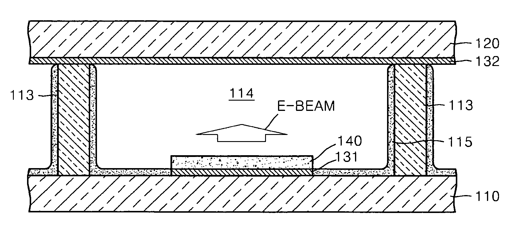
[0046] Referring to FIG. 4, a first substrate 110 which is a lower substrate and a second substrate 120 which is an upper substrate are disposed to oppose each other at regular intervals. The first substrate 110 and the second substrate 120 may be, for example, transparent glass substrates. A plurality of barrier ribs 113 which partition a space between the first substrate 110 and the second substrate 120 form a plurality of light-emitting cells 114 between the first substrate 110 and the second substrate 120. The barrier ribs 113 prevent electrical and optical crosstalk between the light-emitting cells 114. Light-emitting layers 115 are applied to inner walls of the light-emitt...


PUM


Abstract

Provided is a display device. The display device comprises a first substrate and a second substrate opposing each other at regular intervals, a plurality of barrier ribs disposed between the first substrate and the second substrate and partitioning a space between the first substrate and the second substrate to form a plurality of light-emitting cells, an excitation gas filled in the light-emitting cells, a light-emitting layer formed on inner walls of the light-emitting cells, and a first electron emission member disposed in each of the light-emitting cells inside the first substrate, emitting a first electron beam for exciting the excitation gas into the light-emitting cells and including a first electrode formed on an inner surface of the first substrate and a first electron emission source formed of boron nitride bamboo shoot (BNBS) on the first electrode.

Description

CROSS-REFERENCE TO RELATED APPLICATIONS [0001] This application claims the benefit of Korean Patent Application No. 10-2005-0121942, filed on Dec. 12, 2005, in the Korean Intellectual Property Office, the disclosure of which is incorporated herein in its entirety by reference. BACKGROUND OF THE INVENTION [0002] 1. Field of the Invention [0003] The present embodiments relate to a display device, and more particularly, to a display device in which a driving voltage can be reduced and life span can be increased. [0004] 2. Description of the Related Art [0005] Plasma display panels (PDP) which are a type of display devices are apparatuses for forming an image using an electrical discharge. In a PDP, a discharge gas is sealed between two substrates on which a plurality of discharge electrodes is formed, a discharge voltage is applied, phosphors formed in a predetermined pattern are excited by ultraviolet rays generated by the discharge voltage and a desired image is generated. [0006] PDP...

Claims


Application Information

Patent Timeline
IPC IPC(8): H01J17/49H01J11/12H01J11/16H01J11/22H01J11/24H01J11/26H01J11/32H01J11/34H01J11/36H01J11/38H01J11/42H01J11/50H01J17/04H01J17/06
CPCH01J11/12H01J17/49H01J2217/067H01J1/30H01J11/34H01J11/50
Inventor PARK, HYOUNG-BINSON, SEUNG-HYUNJANG, SANG-HUNKIM, GI-YOUNGKIM, SUNG-SOOHATANAKA, HIDEKAZU
Owner SAMSUNG SDI CO LTD
Why Eureka
Try Eureka