Power storage system

a technology of power storage and power supply, applied in the direction of electrochemical generators, secondary cells servicing/maintenance, transportation and packaging, etc., can solve the problems of lowering the operating efficiency, and achieve the effect of ensuring the cell balancing operation, suppressing the deterioration of the batteries, and maintaining the operating efficiency

Active Publication Date: 2011-06-02
MITSUBISHI HEAVY IND LTD +1
View PDF6 Cites 37 Cited by
  • Summary
  • Abstract
  • Description
  • Claims
  • Application Information

AI Technical Summary

Benefits of technology

[0035]According to the present invention, an advantage is afforded in that the cell balancing operation can be surely conducted while suppressing deterioration of the batteries and maintaining the operating efficiency.

Problems solved by technology

With a battery pack configured by connecting, in parallel, a plurality of arms that are configured by connecting a plurality of cells in series, there is a problem in that, when equalization is required for one of the arms, if the equalization is to be conducted by stopping the operation of all arms, the operation of arms that are not required to be equalized is also forced to be stopped, thereby lowering the operating efficiency.

Method used


Image

  • Power storage system
  • Power storage system
  • Power storage system

Examples


first embodiment

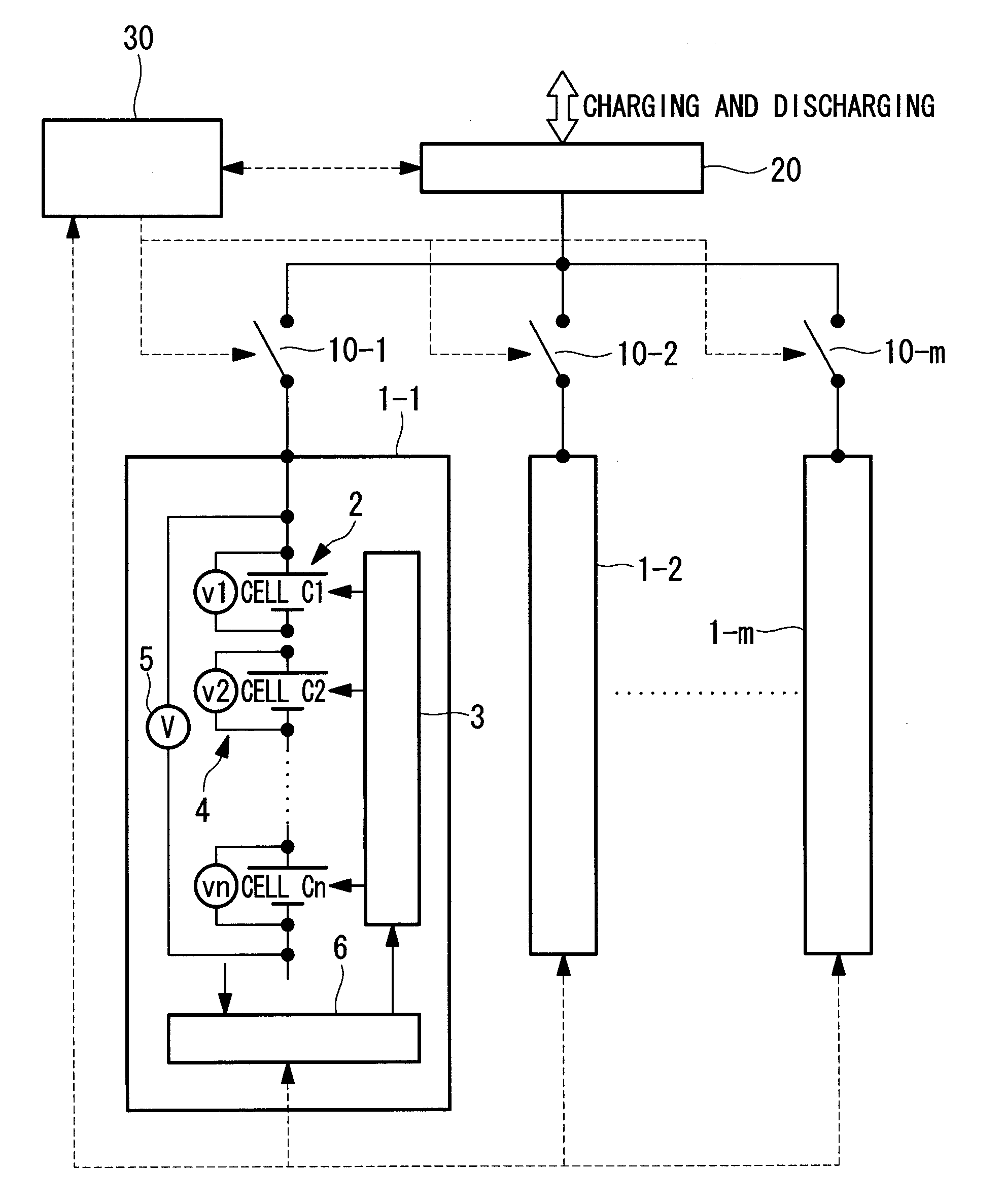
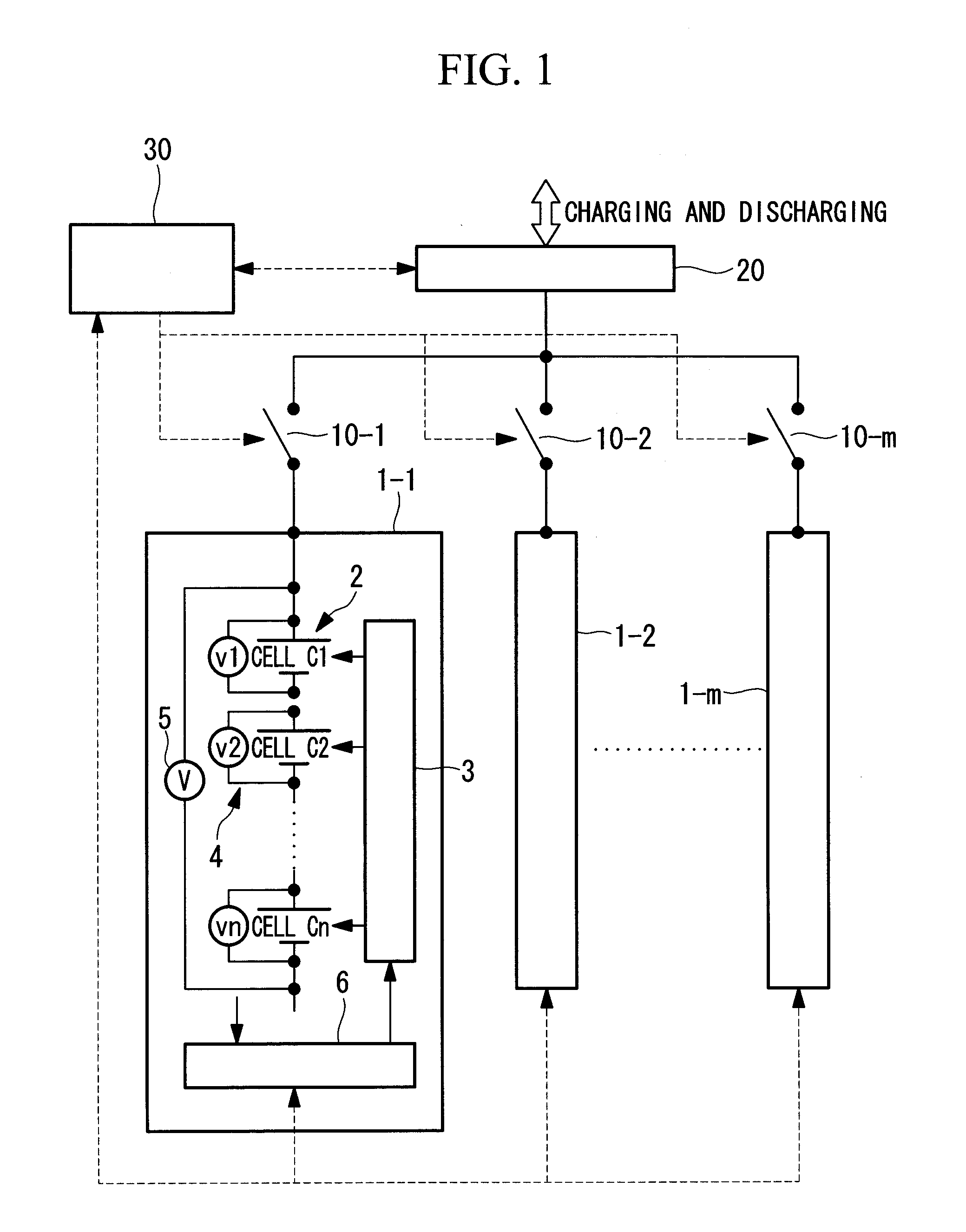
[0060]FIG. 1 is a block diagram showing the schematic configuration of a power storage system according to a first embodiment of the present invention. As shown in FIG. 1, the power storage system is provided with a plurality of arms (battery modules) 1-1, 1-2, . . . and 1-m that are connected in parallel. Each of the arms 1-1, 1-2, . . . and 1-m has the same configuration. The configuration will be explained by using the arm 1-1 as an example. The arm 1-1 is provided with a battery pack 2 in which a plurality of cells (batteries) C1, C2, . . . and Cn are connected in series; a cell balancing circuit 3; cell voltage sensors 4 that measure the voltages of the respective cells C1, C2, . . . and Cn; a battery pack voltage sensor 5 that measures the terminal voltage of the battery pack 2; and an arm control device 6 that controls the cell balancing circuit 3 and so forth.

[0061]The arms 1-1, 1-2, . . . and 1-m are connected to a power converter 20 through respective on / off devices 10-1, ...

second embodiment

[0072]Next, a power storage system according to a second embodiment of the present invention will be described.

[0073]In the above-described first embodiment, the on / off device corresponding to the arm where the cell balance control is being conducted is kept in the open state, thereby setting this arm and the power converter to the disconnected state until the cell balance control is completed. In this embodiment, the configuration of the power storage system is the same as in the above-mentioned first embodiment; however, the opening / closing timing of the on / off device by the system control device 30 is different.

[0074]In the following, the power storage system according to this embodiment will be described with reference to FIG. 1. In addition, also in this embodiment, a description is given assuming that the cell balance control is determined to be required in the arm 1-1.

[0075]In the power storage system according to this embodiment, upon receiving the notification from the arm ...

third embodiment

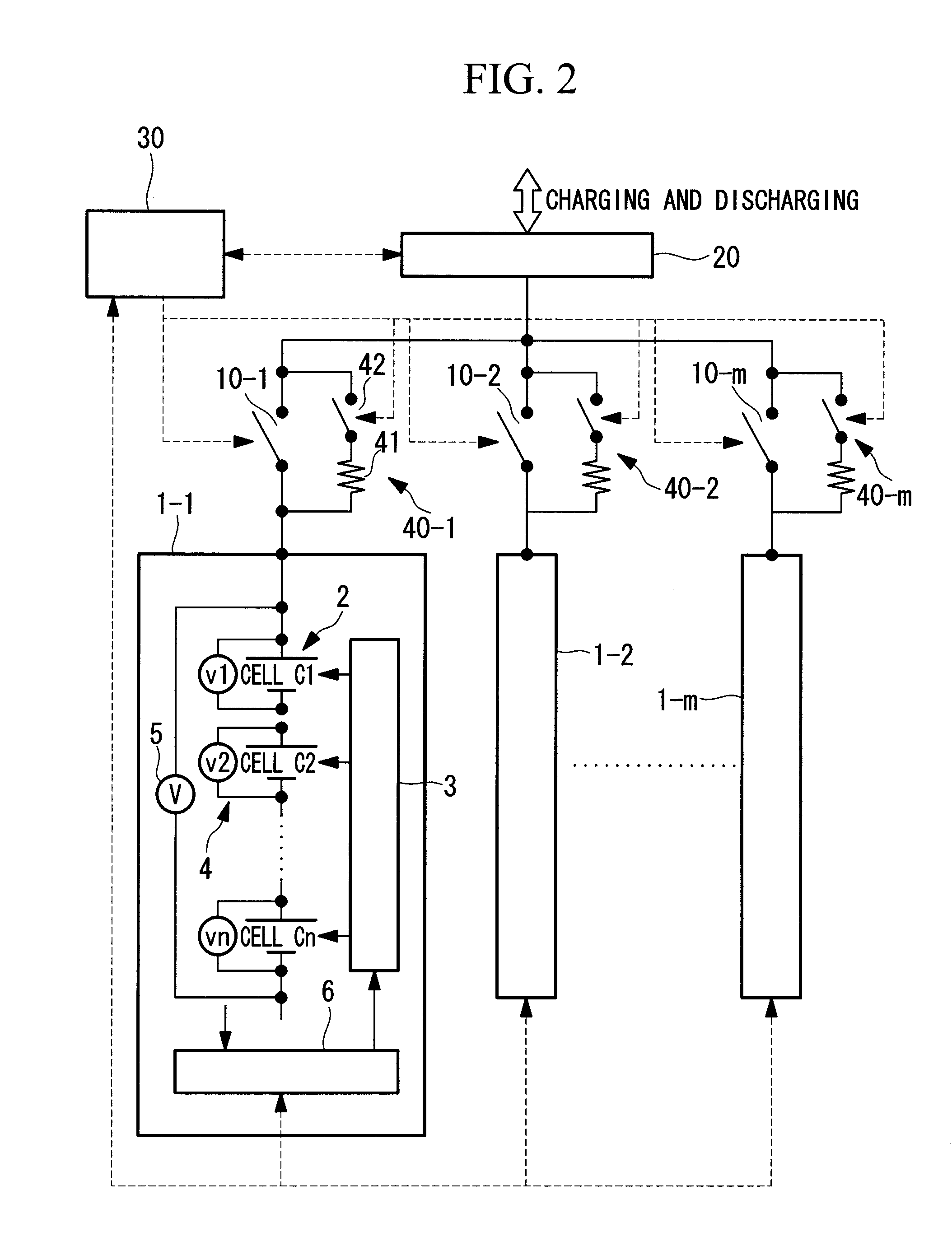
[0079]Next, a power storage system according to a third embodiment of the present invention will be described with reference to FIG. 2. In the following description of the power storage system according to this embodiment, a description of parts that are the same as those in the first embodiment will be omitted, and the differences will be mainly described. In addition, also in this embodiment, a description is given assuming that the cell balance control is determined to be required in the arm 1-1.

[0080]The power storage system in this embodiment differs from the first embodiment in that current control units 40-1, 40-2, . . . and 40-m are connected in parallel to the respective on / off devices 10-1, 10-2, . . . and 10-m. The current control units 40-1, 40-2, . . . and 40-m are each configured so that a resistance element (resistive part) 41 and second on / off device 42 are connected in series.

[0081]With the power storage system having such a configuration, upon receiving a notificat...


PUM


Abstract

An object is to reliably conduct cell balancing operation while suppressing deterioration of batteries and maintaining operating efficiency. When the cell balance control by the cell balancing circuit 3 is started, the system control device 30 sets an on/off device corresponding to the arm where the cell balance control is conducted to the open state; and when the cell balance control is completed, and the difference between the terminal voltage of a battery pack of the arm where the cell balance control has been conducted and the terminal voltages of the battery packs of the other arms falls within a preset allowable range, sets the on/off device, which has been in the open state, to the closed state.

Description

TECHNICAL FIELD[0001]The present invention relates to a power storage system configured by connecting, in parallel, battery modules that are provided with a battery pack in which a plurality of batteries are connected in series.BACKGROUND ART[0002]As a cell balancing method for secondary batteries in the related art, a variety of methods have been proposed and commercialized, such as those utilizing resistance bypass, transformers, flying capacitors, charging power supplies, and so forth. All of these methods equalize the charge states of each of cells in a battery pack in which a plurality of cells are connected in series.[0003]Although the cell balancing methods are generally operated so as to equalize each cell voltage, during the equalization control, there is a possibility that a balance error may be caused due to a voltage drop caused by a charging and discharging current and an internal resistance. When charging or discharging is performed with high current, this error become...

Claims


Application Information

Patent Timeline
Patent Type & Authority Applications(United States)
IPC IPC(8): H02J7/04H02J7/00H02J7/02
CPCH01M10/44H02J7/0014H01M10/441Y02E60/10
Inventor NISHIDA, TAKEHIKOSHIGEMIZU, TETSUROHASHIZAKI, KATSUOADACHI, KAZUYUKIMURAKAMI, SHINJIWADA, YOSHIHIROKURAYAMA, KOUJIFUJITA, HIROFUMI
Owner MITSUBISHI HEAVY IND LTD
Why Eureka
Try Eureka