Antenna device and system including antenna device

a technology of antenna device and antenna device, which is applied in the direction of antenna details, electrically long antennas, antennas, etc., can solve the problems of high manufacturing cost, large transmission loss, and inappropriate passive type for long distance communication

Inactive Publication Date: 2011-06-02
FUJITSU LTD
View PDF10 Cites 51 Cited by
  • Summary
  • Abstract
  • Description
  • Claims
  • Application Information

AI Technical Summary

Benefits of technology

The embodiments discussed herein are related to an antenna device and a system including an antenna device.

Problems solved by technology

As the passive type does not include a power source, the passive type is inappropriate for long distance communications.
However, expensive copper foil is used in the patch conductor of the patch antenna device, and therefore the manufacturing cost is high.
Therefore, the transmission loss is large, and the power needed for communicating with RFID tags may not be sufficiently acquired.
Accordingly, there may be cases where it is not possible to perform communications with RFID tags or to read the identification information, even in areas directly above the antenna device.
This problem particularly tends to occur in areas near the terminating resistor.
In this case, the transmission loss is further increased, and the power may decrease near the terminating resistor.
For this reason, even if the number of branch lines of an antenna device is increased, it may not be possible to increase the areas for communicating with RFID tags.
Similarly, in an antenna device with a transmission line having a meandering shape, the transmission loss increases.
Therefore, in this case also, identification information of RFID tags may not be read even in areas directly above the antenna device.
For this reason, even if the number of bending portions of the meandering shape is increased, it may not be possible to increase the areas for communicating with RFID tags.

Method used


Image

  • Antenna device and system including antenna device
  • Antenna device and system including antenna device
  • Antenna device and system including antenna device

Examples


first embodiment

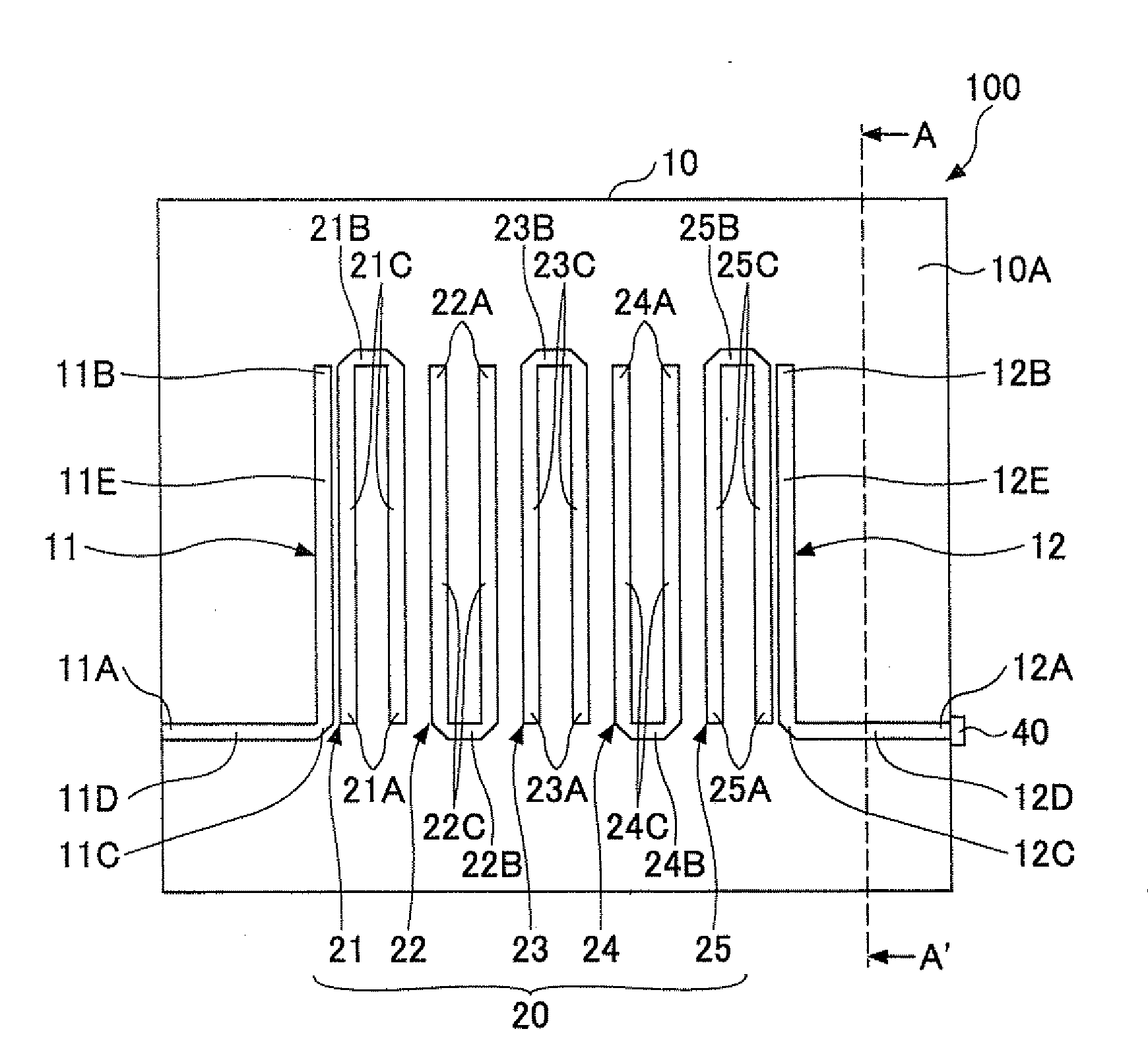
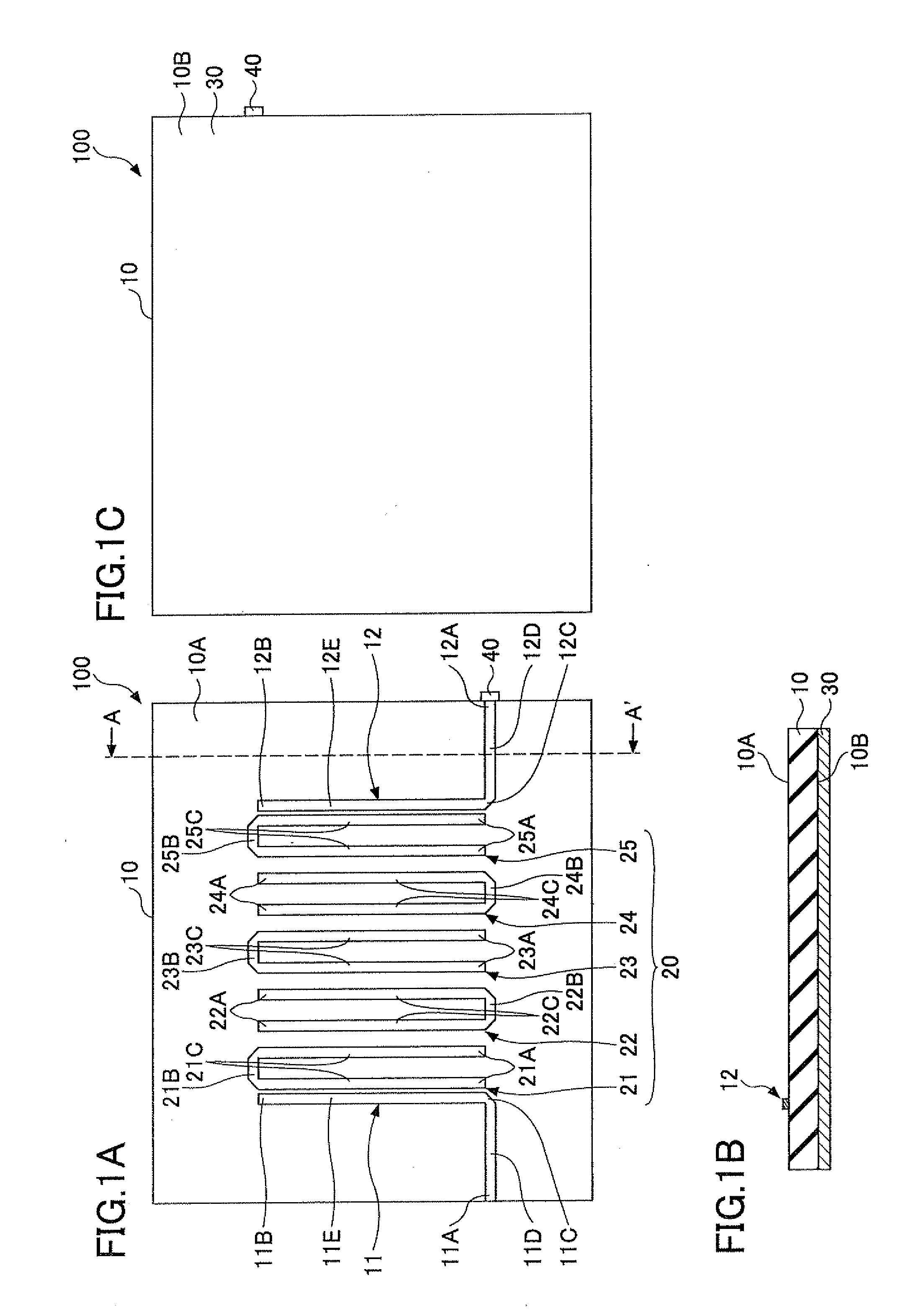
FIGS. 1A through 1C illustrate an antenna device according to a first embodiment of the present invention. FIG. 1A is a plan view, FIG. 1B is cross-sectional view cut along a line A-A′ of FIG. 1A, and FIG. 1C is a bottom view. An antenna device 100 according to the first embodiment is connected to a reader / writer for reading identification information of RFID tags, and performs communications with nearby RFID tags. First, a description is given of the antenna device 100 with reference to FIGS. 1A through 1C, and then the RFID tags and the reader / writer are described with reference to FIGS. 2A through 3.

The antenna device 100 according to the first embodiment includes a printed-circuit board 10, power feeding lines 11 and 12 that are formed on a front surface 10A of the printed-circuit board 10, a resonator 20, and a ground plane 30 formed on a back surface 10B of the printed-circuit board 10.

For example, the printed-circuit board 10 is FR-4 (Flame Retardant Type 4; glass cloth base ...

second embodiment

FIG. 6A is a plan view of an antenna device 200 according to a second embodiment of the present invention, and FIG. 6B illustrates the antenna device 200 connected to the reader / writer 60.

In the antenna device 200 according to the second embodiment, shapes of a resonator 220 and power feeding lines 211 and 212 formed on the front surface 10A of the printed-circuit board 10 are different from those of the resonator 20 and the power feeding lines 11 and 12 of the antenna device 100 according to the first embodiment. Other elements of the antenna device 200 according to the second embodiment are the same as those of the antenna device 100 according to the first embodiment, and therefore, corresponding elements are denoted by the same reference numerals and are not further described. The following descriptions are relevant to differences between the first and second embodiments.

As illustrated in FIG. 6A, the resonator 220 includes five linear resonance elements 221, 222, 223, 224, and 2...

third embodiment

FIG. 7 is a perspective view of an antenna device 300 according to a third embodiment of the present invention.

The antenna device 300 according to the third embodiment is formed by connecting three antenna devices 100 according to the first embodiment in series. In the third embodiment, the three antenna devices 100 are denoted by reference numerals 100A, 100B, and 100C in order to be distinguished from one another. However, the antenna devices 100A, 100B, and 100C are the same as the antenna device 100 according to the first embodiment. Each of the antenna devices 100A, 100B, and 100C includes the resonator 20.

The end part 11A of the antenna device 100A is a power feeding point connected to a reader / writer. The end part 12A of the antenna device 100A is connected to the end part 11A of the antenna device 100B. The antenna device 100B receives power via the antenna device 100A.

The end part 12A of the antenna device 100B is connected to the end part 11A of the antenna device 100C. Th...


PUM


Abstract

An antenna device performs communications with an identification tag by being connected to a reading device that reads identification information of the identification tag. The antenna device includes a first power feeding unit configured to receive power from the reading device; a resonator that is electromagnetically coupled to the first power feeding unit, the resonator having a predetermined bandwidth including a working frequency of the reading device; and a second power feeding unit that is electromagnetically coupled to the resonator, the second power feeding unit being terminated according to a predetermined resistance value.

Description

CROSS-REFERENCE TO RELATED APPLICATIONSThis patent application is based upon and claims the benefit of priority of the prior Japanese Patent Application No. 2009-269850 filed on Nov. 27, 2009, the entire contents of which are incorporated herein by reference.FIELDThe embodiments discussed herein are related to an antenna device and a system including an antenna device.BACKGROUNDConventionally, systems using identification tags such as RFID (Radio Frequency Identification) tags are used for managing various articles.An RFID tag includes an IC (Integrated Circuit) chip storing identification information. When the RFID tag receives reading signals of the RF (Radio Frequency) band from the reader / writer, the IC chip is activated by the power of the received signals. Then, the RFID tag returns identification information to the reader / writer. In this manner, the reader / writer reads identification information from the RFID tag.There are two types of RFID tags. One type is an active type wi...

Claims


Application Information

Patent Timeline
Patent Type & Authority Applications(United States)
IPC IPC(8): H04Q5/22
CPCH01Q1/2216H01Q13/206H01Q11/18
Inventor KAI, MANABUNINOMIYA, TERUHISA
Owner FUJITSU LTD
Why Eureka
Try Eureka