Method of and system for determining a head-motion/gaze relationship for a user, and an interactive display system

a technology of eye-gaze relationship and interactive display system, which is applied in the field of method and system for determining a head-motion/gaze relationship for a user, and an interactive display system, can solve the problems of complex and expensive systems, eye-gaze tracking becomes more difficult to perform with accuracy, and the user would probably just be perceived as irritating, etc., to achieve comfortable looking, wide separation, and more accurate calibration

Inactive Publication Date: 2011-06-02
KONINKLIJKE PHILIPS ELECTRONICS NV
View PDF10 Cites 92 Cited by
  • Summary
  • Abstract
  • Description
  • Claims
  • Application Information

AI Technical Summary

Benefits of technology

[0030]In a preferred embodiment of the invention, the first target and the second target comprise distinct or separate items in the display area. In a shop window, for example, these objects can be products available in the shop. In an exhibit display case, the items can be exhibits for which descriptive information can be presented. Preferably, the first and second targets are the two most widely separated items in the display area. These target items can be defined in a system configuration procedure, and used in all subsequent user calibrations. For a user positioned centrally in front of the display area, this wide separation allows a more accurate calibration. However, a user can evidently position himself at any point in front of the display area, for example, to one side of the display area. Therefore, in a more flexible approach, the first and second targets can be allocated after the user has been detected, and according to the user's position in front of the display area. This ensures that, for a particular user, the target items can be comfortably looked at, and the angular separation of the target items is maximized from the point of view of the user, thus ensuring a more accurate head pose measurement.
[0031]A pertinent aspect of the invention is that the user is guided or encouraged to look at the target items so that the relationship between this user's head heading and gaze heading can be determined. Therefore, in a further preferred embodiment of the invention, a target in the display area is visually emphasised to attract the user's gaze towards that target. One way of emphasising a target item to attract the user's attention might be to have that item mounted on a turntable, which is then caused to rotate for an interval of time. In an alternative approach, visually emphasising an object or item can be done simply by highlighting that object while other objects are not highlighted. When using lighting to emphasise an object, the highlight effect could have a distinct colour, or could make use of conspicuous eye-catching effects such as a pulsating lighting effect, lighting being directed around the product, changing colours of light, etc. The aim of the visual emphasis is to intentionally encourage the user to look at the targets in turn. For a user interested in the contents of a display area, it can safely be assumed that the attention of the user will be drawn to the visually emphasised target. When one item of a number of items is visually emphasised, it is a natural reaction for the user to look at that emphasised item. The effectiveness can be increased if the visual emphasis occurs suddenly, i.e. with an abrupt onset. The user's head can be observed while the first and then the second target are emphasized, and the relationship between the monitored head movements and the assumed eye gaze direction can be determined using the known position of the user and the target items. The type of calibration described here is entirely passive or implicit, i.e. apart from the highlighting, the user is not given any indication that a particular procedure is being carried out.
[0032]The visual emphasis of the targets need not be limited to mere highlighting using spotlights or the like. With modern projection techniques, more interesting ways of drawing the user's attention to an item are given. Therefore, in a particularly preferred embodiment of the invention, a virtual cursor is projected in the display area to direct the user's gaze at a specific target. For example, an image of an arrow could be projected within the display area, dynamically guiding the user to look first at one target, and then at another target. The ‘cursor’ can also be an easily understandable symbol such as a pair of eyes that ‘look’ in the direction of the target item being highlighted, a finger that points in that direction, or a pair of footprints ‘walking’ in that direction. The virtual cursor can move across the display area towards the first target, which is then highlighted, so that the user's gaze can be assumed to rest on the first target. After a short interval, the virtual cursor can proceed to travel towards the second target, which is then also highlighted for a brief interval. This preferred embodiment allows an explicit calibration in which the user is aware that a procedure is being carried out in which he can participate. The advantage of this more entertaining approach is that it is more reliable in ensuring that the user actually looks at a target item, and that his focus of attention is not drawn to something else in the display area.

Problems solved by technology

Presenting the user with information that is of no interest to him would probably just be perceived as irritating.
For a ‘remote’ environment such as shop window or museum exhibit, however, in which a person could be standing anywhere in front of the display—in the middle, to one side, close by, or at a distance, eye-gaze tracking becomes more difficult to perform with accuracy.
At present, such systems are complex and expensive and are generally only applied in research labs.
This is rarely the case, as will be explained below, and the disadvantage is that most users would need to exaggerate their head movement in order to successfully interact with the system.
Such unsatisfactory interaction might well lead to a rejection of this type of application.

Method used


Image

  • Method of and system for determining a head-motion/gaze relationship for a user, and an interactive display system
  • Method of and system for determining a head-motion/gaze relationship for a user, and an interactive display system
  • Method of and system for determining a head-motion/gaze relationship for a user, and an interactive display system

Examples


Embodiment Construction

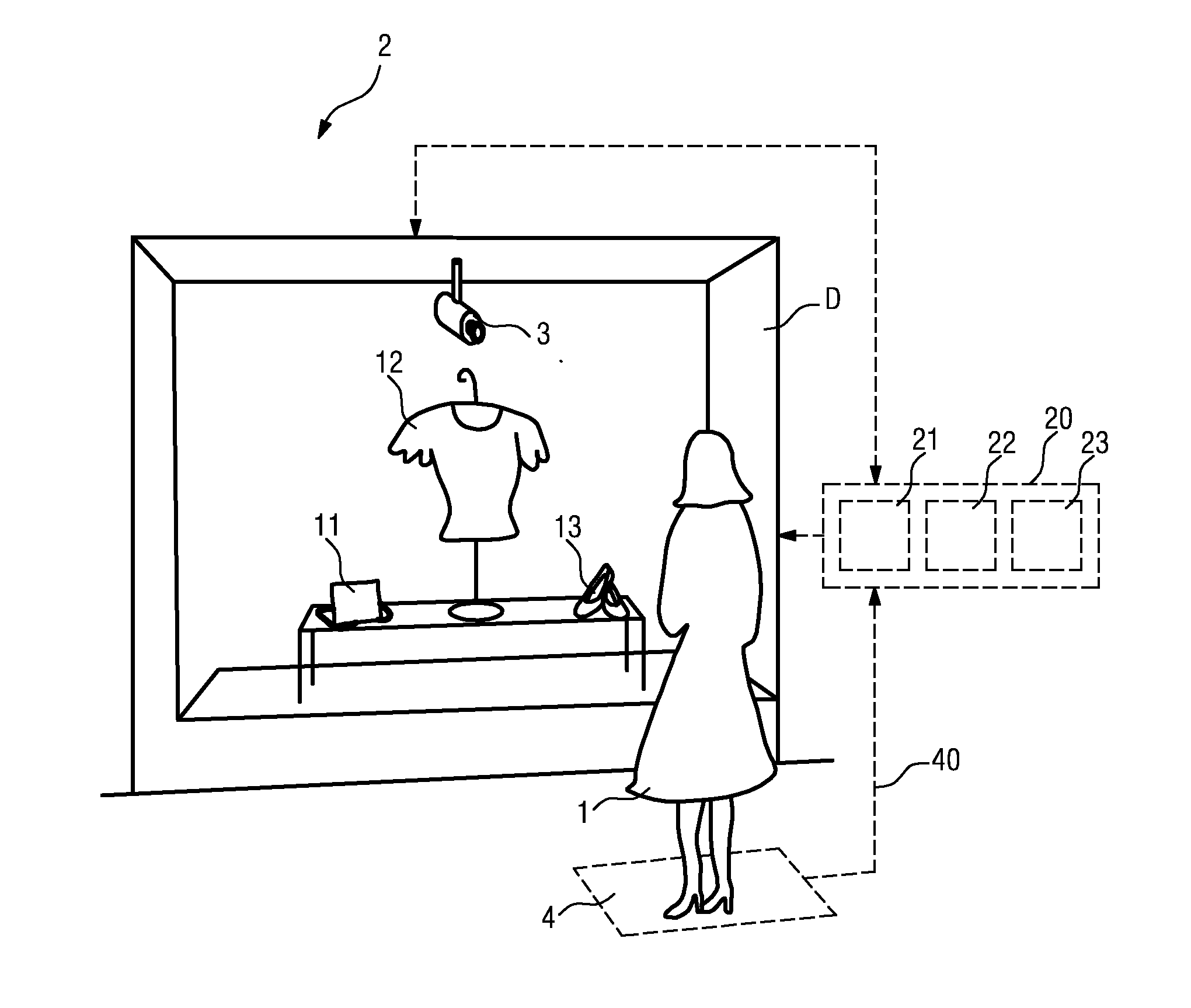
[0054]FIG. 1 shows a user 1 in front of a display area D, in this case a potential customer 1 in front of a shop window D. For the sake of clarity, this schematic representation has been kept very simple. In the shop window D, items 11, 12, 13 are arranged for display. A detection means 4, in this case a pressure mat 4, is located at a suitable position in front of the shop window D so that the presence of a potential customer 1 who pauses in front of the shop window D can be detected. An observation means 3, or head tracking means 3, with a camera arrangement is positioned in the display area D such that the head motion of the user 1 can be tracked as the user 1 looks at one or more of the items 11, 12, 13 in the display. The head tracking means 3 can be activated in response to a signal 40 from the detection means 4 delivered to a control unit 20. Evidently, the head tracking means 3 could, if appropriately realized, be used in lieu of the detection means 4 for detecting the prese...


PUM


Abstract

The invention describes a method of determining a head-motion/gaze relationship for a user (1), which method comprises the steps of allocating at least one first target (T1) and at least one second target (T2) in a display area (D); attracting the user's gaze towards a first target (T1) and observing the user's head (H) to obtain a first head orientation measurement value (M1). The method further comprises the steps of subsequently attracting the user's gaze towards a second target (T2) and observing the user's head (H) to obtain a second head orientation measurement value (M2); and analysing the head orientation measurement values (M1, M2) to obtain a head-motion/gaze relationship (R) for that user (1). The invention further describes an interactive display system (2), and a method of performing a gaze-based interaction between a user (1) and an interactive display system (2).

Description

FIELD OF THE INVENTION[0001]The invention describes a method of and a system for determining a head-motion / gaze relationship for a user. The invention also describes an interactive display system, and a method of performing a gaze-based interaction between a user and an interactive display system.BACKGROUND OF THE INVENTION[0002]In recent years, developments have been made in the field of interactive shop window displays, which are capable of presenting product-related information using, for example, advanced projection techniques, in a more interesting manner to a potential customer looking at the display. The aim of such an interactive shop window is to present information about the product or products that specifically interest a potential customer. In this way, the customer might be more likely to enter the shop and purchase the item of interest. Also, presenting products and product-related information in this way contributes to a more interesting shopping experience. An advant...

Claims


Application Information

Patent Timeline
Patent Type & Authority Applications(United States)
IPC IPC(8): G06F3/033
CPCG06F3/013G06F3/012
Inventor LASHINA, TATIANA ALEKSANDROVNAVAN LOENEN, EVERT JANMUBIN, OMAR
Owner KONINKLIJKE PHILIPS ELECTRONICS NV
Why Eureka
Try Eureka