
Fiber Optic Module Assembly and Associated Methods

a fiber optic module and fiber optic module technology, applied in the field of fiber optic module assemblies, can solve the problems of increasing downtime and expense, difficult installation, and a full-populated data center, and achieve the effect of facilitating the installation of the fiber optic module assembly

Inactive Publication Date: 2011-06-02
CORNING CABLE SYST LLC
View PDF86 Cites 99 Cited by
  • Summary
  • Abstract
  • Description
  • Claims
  • Application Information

AI Technical Summary

Benefits of technology

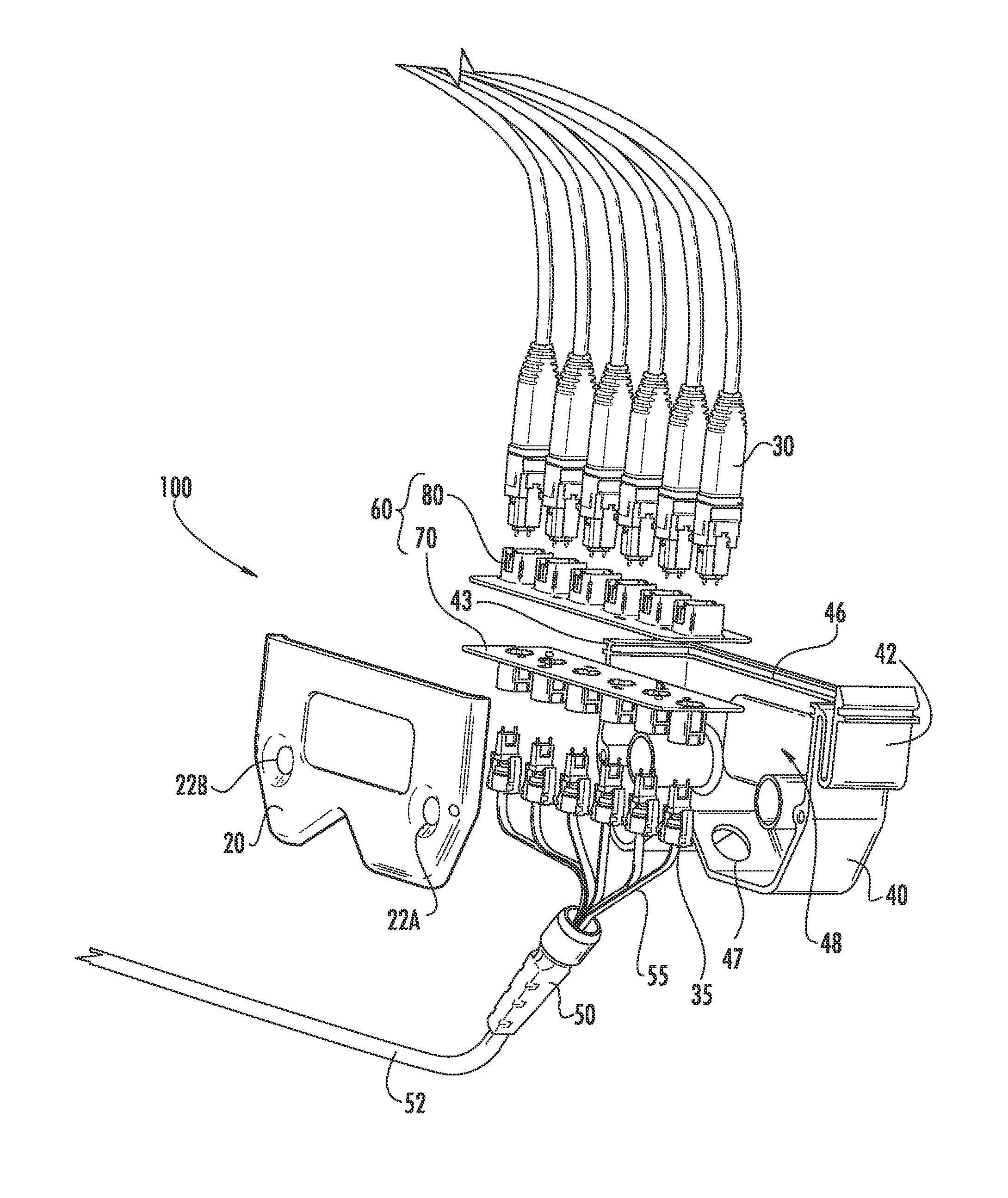
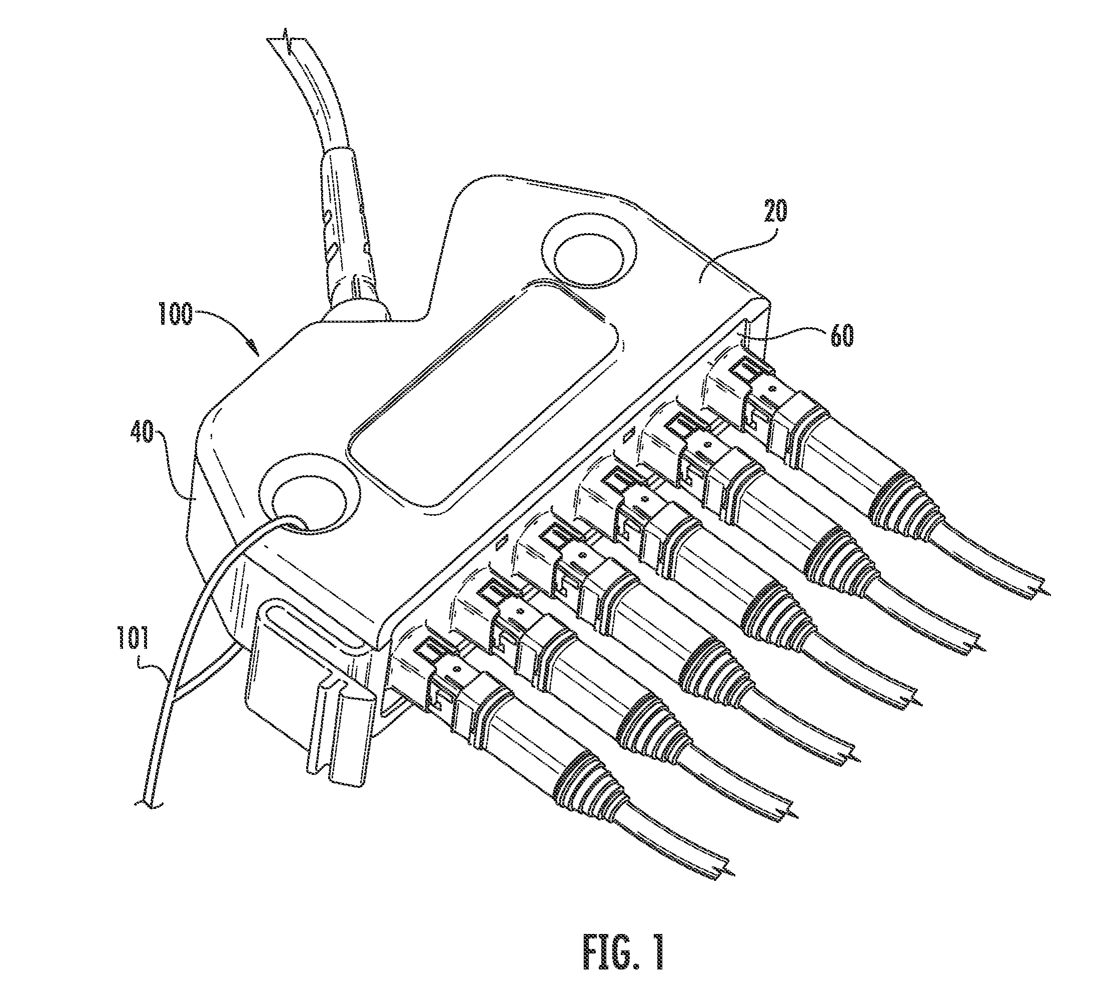
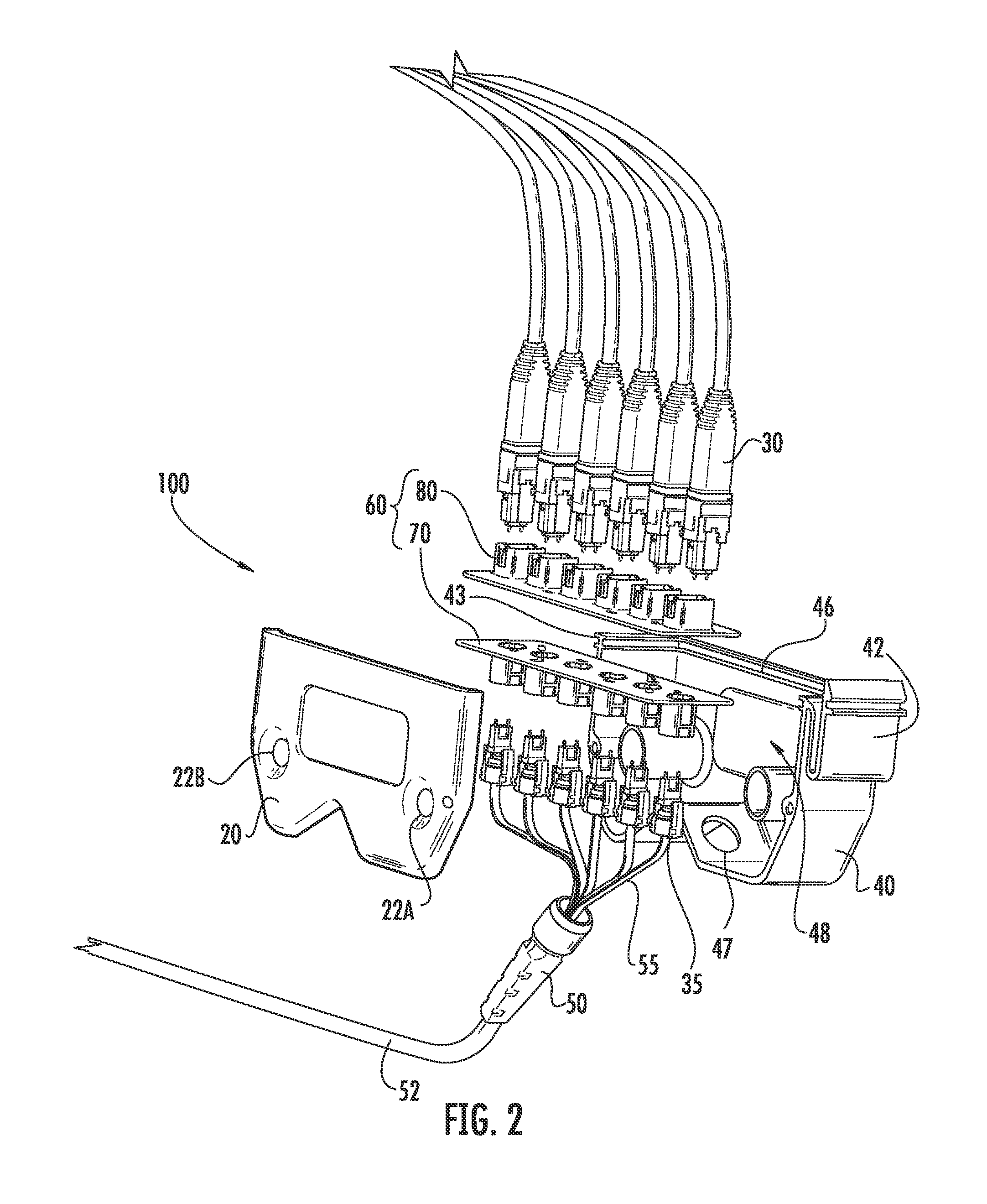
[0007]In one embodiment, the disclosure is directed to a fiber optic module assembly, defining a pulling feature. The fiber optic module assembly has a housing assembly receiving a portion of a fiber optic cable assembly and receives a plurality of fiber optic connectors for optically mating to a plurality of optical connector assemblies on the fiber optic cable assembly. The pulling feature facilitates installation of the fiber optic module assembly. In other embodiments the fiber optic module assembly further includes a latching feature for attaching the fiber optic module assembly to a mounting structure.

Problems solved by technology

However, a fully populated data center can present a challenge for moves, adds and changes.
More capacity and updated hardware are frequently needed and can be difficult to install, increasing downtime and expense.

Method used


Image

  • Fiber Optic Module Assembly and Associated Methods
  • Fiber Optic Module Assembly and Associated Methods
  • Fiber Optic Module Assembly and Associated Methods

Examples


embodiment 160

[0038]Other embodiments of the pulling feature are possible, such as shown in FIG. 10A and FIG. 15A. Specifically, FIG. 10A shows a loop pulling feature 91 defined by another embodiment 90 of a fiber optic module assembly and FIG. 15A shows cover pulling feature 162 defined by a protective cover 161 on a further embodiment 160 of a fiber optic module assembly. Consequently, the pulling feature for the fiber optic module assembly may include a loop, a hook and a through aperture and may be incorporated on any of the embodiments.

[0039]The fiber optic module assembly of the disclosure may be attached directly to any suitable mounting structure. The mounting structure may be a bracket, a box, a raceway, or the like. By way of example, the mounting structure may be a rack mounted shelf in a data center, such as a Pretium™ Rack-mountable 4U Housing, commercially available from Corning Cable Systems, LLC, Hickory N.C., for use with other fiber optic module assemblies as a patch panel. In s...

embodiment 90

[0052]FIGS. 11A and 11B show two views of an alternate embodiment 90 of the fiber optic module assembly mounted on a front of a mounting structure, in this embodiment a 4U data center shelf with a swinging front panel 93 (further enabled by bend insensitive optical fiber). Alternate embodiment 90 may have the articulate strain relief boot 140 assembly attached to the swinging front panel 93, with articulated strain relief boot 140 in the installed position. Cable gather 92 prevents fiber optic cable 52 from dangling below the level of the floor of the 4U data center shelf.

[0053]Another 160 fiber optic module assembly is shown in FIG. 15A having fiber optic cable 52 connectorized by rugged connector 53. FIG. 15B reveals the interior 165 of another 160 fiber optic module assembly having partial MTP connectors installed within MTP adapters 166. Articulated strain relief boot 140 may be housed by protective cover 161 and is shown in the pulling position. A flexible strain relief boot 54...


PUM


Abstract

A fiber optic module assembly that may be pulled from a first location to a second location by a pulling means, the module assembly defining a pulling feature. The assembly may further be installed directly into a mounting structure for use as a patch panel. The fiber optic module assembly may be attached in a vertical orientation, facilitated by an articulated strain relief boot that pivots and rotates for cable management, which reduces the vertical footprint of the fiber optic module assembly. Embodiments of the fiber optic module assembly may be connected to the rear or side of a mounting structure for optical connection to pigtailed modules. The fiber optic module assembly may have a modular connector interface for mating dissimilar fiber optic connector assemblies.

Description

PRIORITY APPLICATION[0001]This application claims the benefit of U.S. Provisional Application Ser. No. 61 / 265,047 filed on Nov. 30, 2009 and entitled “Fiber Optic Module Assembly and Associated Methods,” the entire contents of which are hereby incorporated by reference.RELATED APPLICATION[0002]The present application is related to U.S. Provisional Application Ser. No. 61 / 265,038 filed on Nov. 30, 2009 and entitled “Articulated Strain Relief Boot on a Fiber Optic Module and Associated Methods,” the entire contents of which are hereby incorporated by reference.FIELD[0003]The disclosure relates generally to fiber optic assemblies and more particularly to fiber optic module assemblies which may be used in fiber optic assemblies.TECHNICAL BACKGROUND[0004]Telecommunications systems use data centers to collect, process and redistribute large amounts of electronic and digital information. Fiber optics has ushered in a faster and more efficient means of performing this basic function, enabli...

Claims


Application Information

Patent Timeline
IPC IPC(8): G02B6/38G02B6/46
CPCG02B6/3825G02B6/4441G02B6/3887G02B6/38875G02B6/4478
Inventor LEWALLEN, C. PAULLUTHER, JAMES P.MELTON, STUART R.NORRIS, MARTIN E.THEUERKORN, THOMAS
Owner CORNING CABLE SYST LLC
Learn More