Exposure head and image forming apparatus

a technology of image forming apparatus and exposure head, which is applied in the direction of electrographic process apparatus, printing, instruments, etc., can solve the problems of complicated light-emitting element light-emitting timing control, difficulty in adjusting the spacing of the three light-emitting element rows at equal distances and difficulty in adjusting the spacing of the three light-emitting element rows at equal distances (regulatory intervals) in the secondary scanning direction. to achiev

Inactive Publication Date: 2011-06-02
SEIKO EPSON CORP
View PDF3 Cites 1 Cited by
  • Summary
  • Abstract
  • Description
  • Claims
  • Application Information

AI Technical Summary

Benefits of technology

[0009]An advantage of some aspects of the invention is to provide a technology to simplify light-emitting timing control of light-emitting elements.

Problems solved by technology

However, it is difficult to increase the dimensions of the respective light-emitting elements sufficiently only by arranging the plurality of light-emitting elements in line.
However, there is a problem as described below in order to arrange three or more light-emitting element rows.
However, in a configuration in which the three light-emitting element rows are disposed in the secondary scanning direction, arrangement of the three light-emitting element rows at equal distances (regular intervals) in the secondary scanning direction may be difficult if an attempt is made to avoid the interference between the light-emitting element rows and to secure the dimensions of the light-emitting elements to be sufficiently large.
However, in order to cause the respective light-emitting elements arranged in the three light-emitting element rows in this manner to emit lights at timings according to the movement of the surface of the latent image carrier in the secondary scanning direction, the necessity to cause the three light-emitting elements which belong to different light-emitting element rows to emit lights at different timings arises, so that light-emitting timing control of the light-emitting elements becomes complicated.
Therefore, as described above, the necessity to cause the first light-emitting element, the third light-emitting element, and the fourth light-emitting element to emit lights at timings different from each other arises, so that light-emitting timing control may be complicated.
Therefore, as described above, in order to cause the first light-emitting element, the second light-emitting element, and the fourth light-emitting element to emit light at timings according to the movement of the surface of the photosensitive drum in the orthogonal direction, the necessity to cause the first light-emitting element, the third light-emitting element, and the fourth light-emitting element to emit lights at timings different from each other arises, so that the light-emitting timing control may be complicated.

Method used


Image

  • Exposure head and image forming apparatus
  • Exposure head and image forming apparatus
  • Exposure head and image forming apparatus

Examples


first embodiment

A. First Embodiment

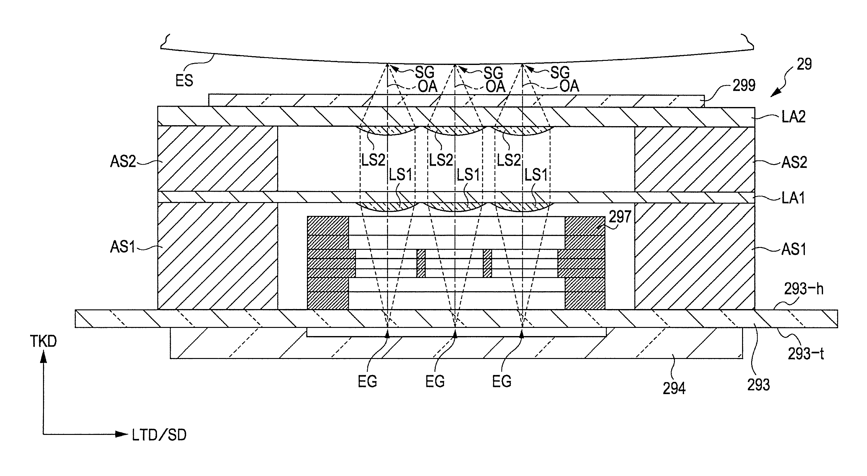
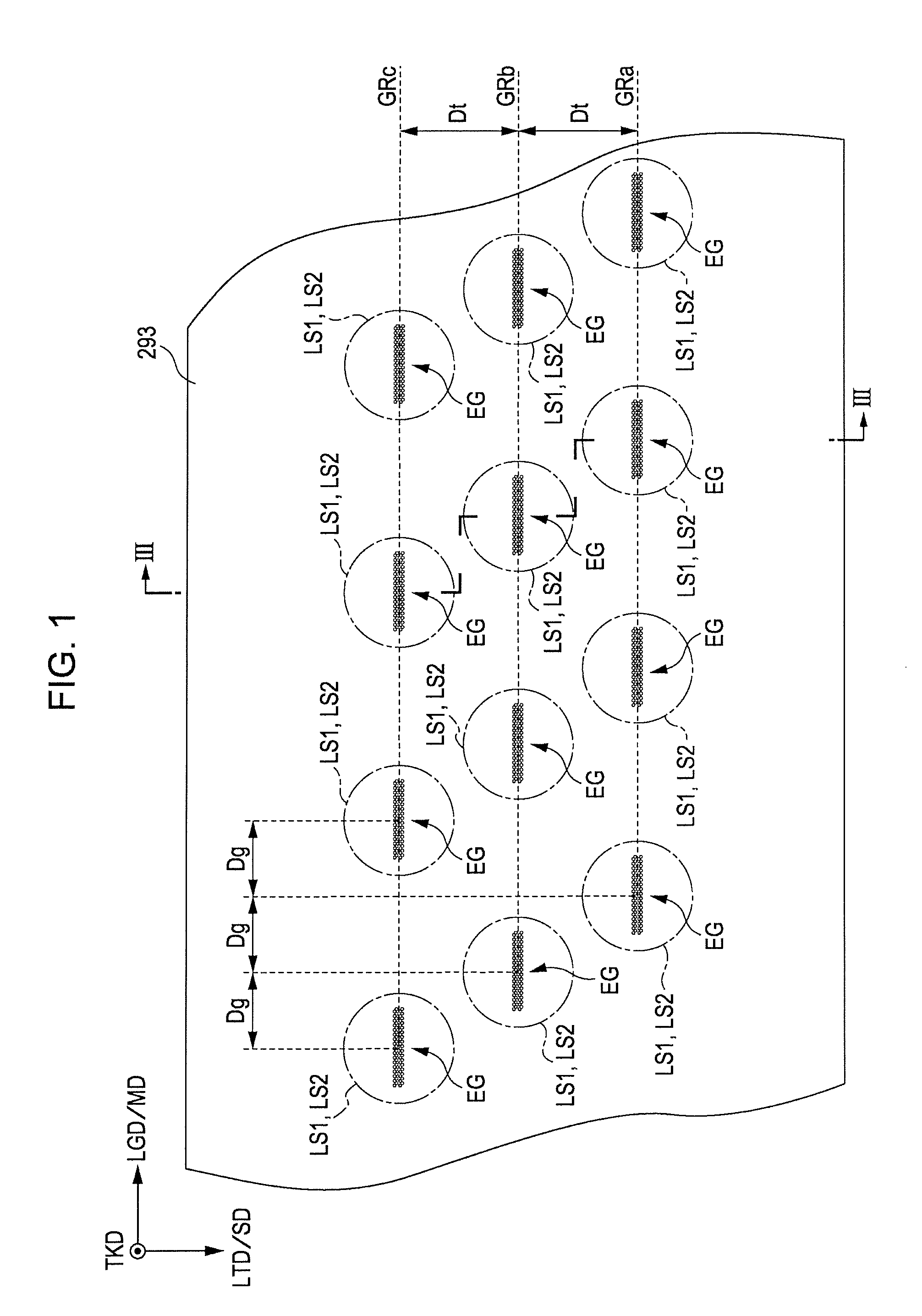
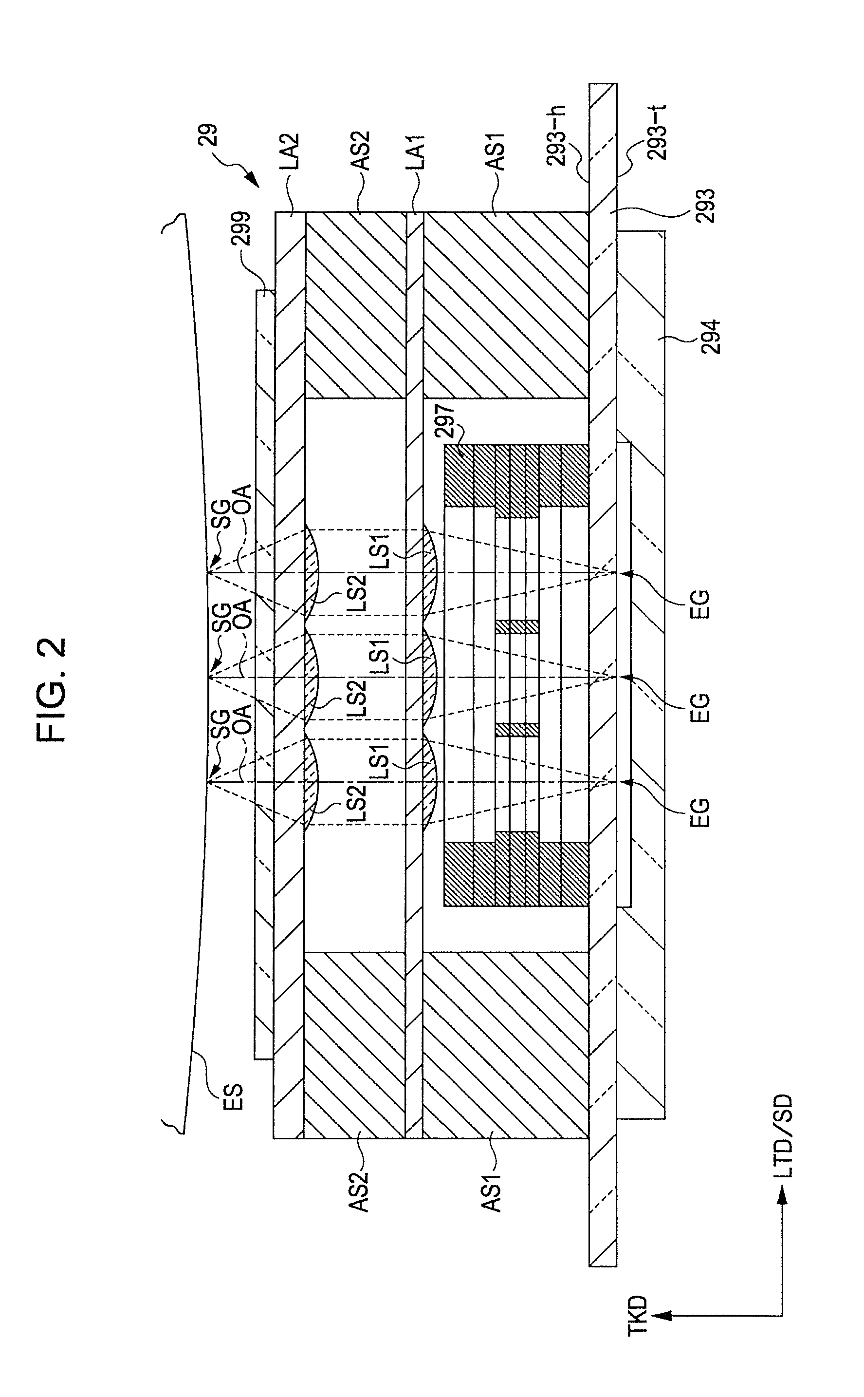
[0079]FIG. 1 and FIG. 2 are drawings showing an example of a line head to which the invention can be applied. In particular, FIG. 1 is a plan view of a positional relationship between light-emitting elements and lenses provided on a line head 29 viewed in a thickness direction TKD of the line head 29. FIG. 2 is a partial stepped cross-sectional view of the line head 29 taken along the line III-III (stepped chain double-dashed line in FIG. 1), which corresponds to a case where the cross-section is viewed in a longitudinal direction LGD of the line head 29. The line head 29 is long in the longitudinal direction LGD and short in a width direction LTD, and has a predetermined thickness (height) in the thickness direction TKD. In the drawings shown below including FIG. 1 and FIG. 2, the longitudinal direction LGD, the width direction LTD, and the thickness direction TKD of the line head 29 are shown as needed. These directions LGD, LTD, and TKD are orthogonal or substa...

second embodiment

B. Second Embodiment

[0122]FIG. 20 is a drawing showing an example of an image forming apparatus to which the line head described above can be applied. FIG. 21 is a block diagram showing an electric configuration of the apparatus shown in FIG. 20. In the second embodiment, an example of the image forming apparatus provided with the above-described line head 29 will be described with reference to these drawings. An image forming apparatus 1 includes four image forming stations 2Y (for yellow), 2M (for magenta), 2C (for cyan), and 2K (for black) which form a plurality of images in different colors. Then, the image forming apparatus 1 is capable of being selectively operated in a color mode in which four colors of toner of yellow (Y), magenta (M), cyan (C), and black (K), are overlapped to form a color image and in a monochrome mode in which only black (K) toner is used to form a monochrome image.

[0123]In the image forming apparatus, when an image formation command is given from an exte...


PUM


Abstract

A exposure head includes: a light-emitting element substrate including a first light-emitting element configured to emit light, a second light-emitting element disposed in a first direction of the first light-emitting element, a third light-emitting element, and a fourth light-emitting element disposed so as to satisfy the following relationship; Dr12:Dr23=1:m (l≠m) where, l: positive integer number, m: positive integer number, Dr12: distance between the first light-emitting element and the third light-emitting element in the direction orthogonal to the first direction, Dr23: distance between the third light-emitting element and the fourth light-emitting element in the direction orthogonal to the first direction, and an imaging optical system configured to image lights emitted from the first light-emitting element, the second light-emitting element, the third light-emitting element, and the fourth light-emitting element.

Description

BACKGROUND[0001]1. Technical Fields[0002]The present invention relates to an exposure head configured to image lights from light-emitting elements by an imaging optical system and an image forming apparatus using the exposure head.[0003]2. Related Art[0004]In JP-A-2009-098613, an exposure head including a light-emitting element group having a plurality of light-emitting elements aligned in a primary scanning direction and an imaging optical system opposing the light-emitting element group is disclosed. In other words, the exposure head is configured to irradiate an exposed surface with light spots by imaging the lights from the light-emitting elements by the imaging optical system. Then, by imaging the lights from the plurality of light-emitting elements in the light-emitting element group by the imaging optical system, a plurality of the spots are directed to different positions from each other in the primary scanning direction, so that the portions irradiated with the respective s...

Claims


Application Information

Patent Timeline
Patent Type & Authority Applications(United States)
IPC IPC(8): G03G15/043
CPCG03G15/326G03G15/04045B41J2/45
Inventor SOWA, TAKESHIIKUMA, KENKOIZUMI, RYUTAINOUE, NOZOMU
Owner SEIKO EPSON CORP
Why Eureka
Try Eureka