Piling barge

a technology of piling barge and sluice barge, which is applied in the field of piling barge to achieve the effects of facilitating the adjustment of the pile position, and improving the working efficiency of the piling barg

Inactive Publication Date: 2011-06-02
SANY ELECTRIC CO LTD
View PDF13 Cites 12 Cited by
  • Summary
  • Abstract
  • Description
  • Claims
  • Application Information

AI Technical Summary

Benefits of technology

[0009]A second object of the present invention is to provide a piling barge with high piling efficiency.
[0027]In a still further technical solution, the lower end of the boom is hingedly connected, and the piling barge also has a luffing winch mechanism, through which the luffing angle of the boom, i.e., the angle between the boom and the hull may be changed; the combination of the luffing winch mechanism and the luffing oil cylinder allows to further precisely adjust the contacting point between the pile and the seabed ground as well as the inclination angle of the pile, therefore improving the working efficiency of the piling barge.

Problems solved by technology

The existing piling barge presents the following disadvantages:
1. It is difficult for the piling barge to perform piling for sea areas with mollisol ground at the seabed. The seabed ground of a tidal flat or a neritic zone usually has silt layers, which form mollisol ground. Reference is made to FIG. 1, which is a schematic diagram of the load bearing of a supporting leg of the existing piling barge when being supported on the seabed ground. If the ground of the operating sea area is a mollisol ground, the supporting leg 200 will be trapped into the mollisol ground 300, which in turn generates two force acting on the lower end of the supporting leg 200, i.e., a supporting force F1 to a bottom surface of the supporting leg 200, and a friction force F2 to side surfaces of the supporting leg 200, the resultant force of these two forces being the supporting force that could be provided to the hull 100 by the supporting leg 200. Due to the fact that the mollisol ground has fluidity, ground grains at the bottom surface of the supporting leg 200 will flow to the periphery when receiving force from the supporting leg 200. At this point, the mollisol ground 300 fails to generate a large force to act on the bottom surface of the supporting leg 200, which results a smaller supporting force F1; and for the same reason, the friction force F2 is also severely limited by the fluidity of the mollisol ground 300. As a result, when the operating sea area is a mollisol ground 300, it is difficult for the supporting leg 200 to provide a large supporting force to the hull 100, and thus the piling device on the piling barge could not operate stably, and it would be difficult to implement the piling operation on sea areas with mollisol ground. Moreover, when the supporting leg 200 is to be extracted from the mollisol ground 300, the friction force F2 would be applied to the supporting leg 200 in an opposite direction to make it difficult to extract the supporting leg 200 from the mollisol ground 300, resulting in difficulty in relocating of the piling barge.
However, they both are impractical, because this may not only bring about increase in the overall size and thus the manufacturing and using costs of the piling barge, but also make it difficult to extract the supporting leg 200 out of the mollisol ground 300 and thus make it impossible to relocate the piling barge due to a large friction force F2.
2. Low working efficiency.
In the pile-turning or pile-sinking of the existing piling barge, the positioning is usually made by way of windlassing, which leads to long positioning period and reduced operating efficiency of the piling barge.

Method used


Image

  • Piling barge
  • Piling barge
  • Piling barge

Examples


second embodiment

[0049]Reference is made to FIG. 7, which is a structural schematic view of the supporting leg in the piling barge provided by the prevent invention.

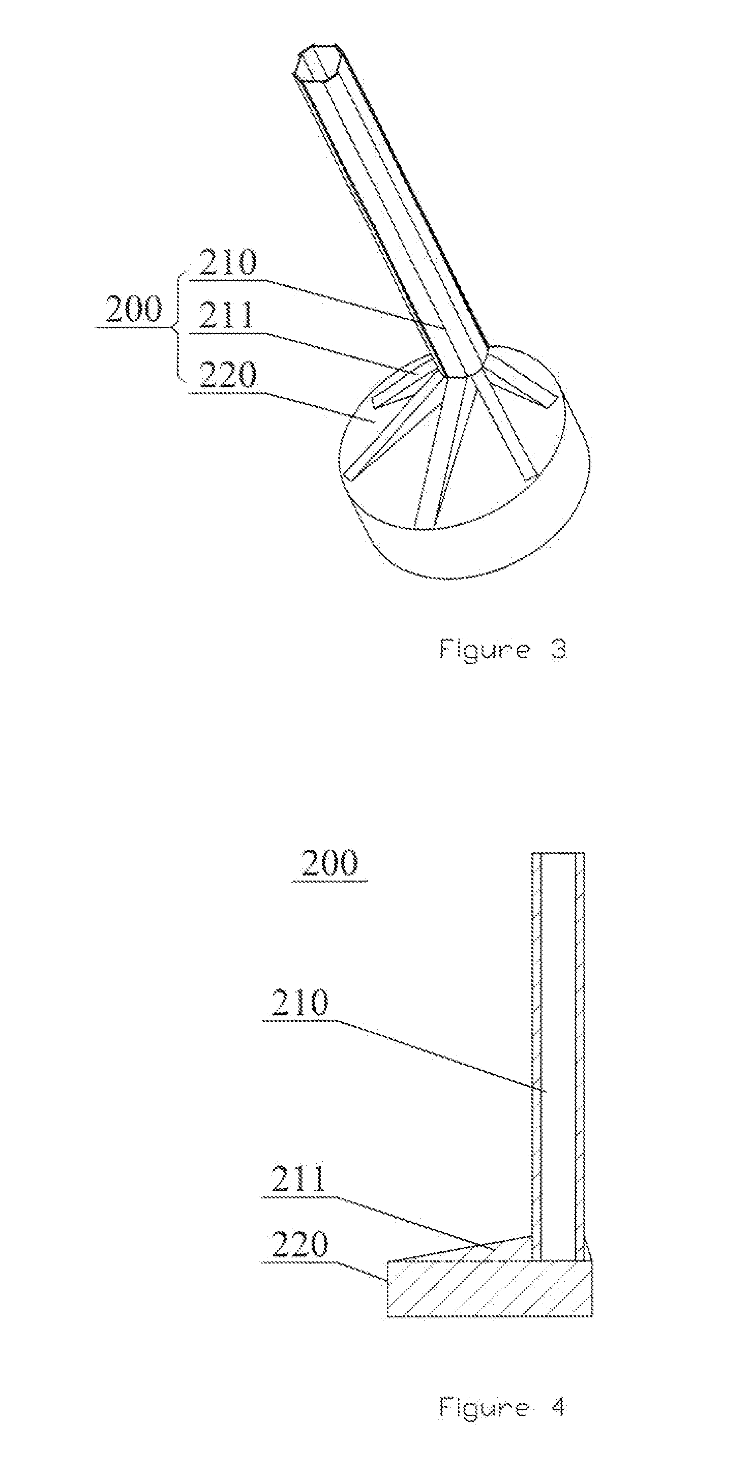
[0050]As compared with the first supporting leg, one of the differences in the second supporting leg is that the supporting base 220 includes a cavity 221 having an opening at the bottom surface of the supporting base 220. Following is the working principle of the supporting leg 200. When the supporting leg 200 needs to be lowered and supported on the seabed ground, a suitable charging and discharging pump may be used to depressurize the cavity 221, discharge air and water inside the cavity 221, and thus establish a negative pressure therein, such that the supporting leg 200 is lowered smoothly and sunk through to the seabed ground, therefore providing a supporting force for the hull 100; when the supporting leg 200 needs to be separated from the mollisol ground 300 after a predetermined offshore operation being finished, the charging an...

third embodiment

[0053]It can be appreciated that the cavity 221 may be pressurized or depressurized, as long as the outer port of the charging and discharging passage 222 is positioned on the outer surface of the supporting base 220 and the inner port thereof is on the wall of the cavity 221. Therefore, the outer port of the charging and discharging passage 222 may be positioned at other portions of the outer surface of the supporting base 220. As shown in the structural schematic view of the supporting leg in the piling barge provided by the prevent invention in FIG. 8, herein, the outer port of the charging and discharging passage 222 is positioned between the reinforcing ribs 211 at the outer surface of the supporting base 220. In this way, the charging and discharging passage 222 can be connected with the charging and discharging pump provided on the hull 100 through the delivery pipe 230. Also, the charging and discharging pump may be disposed directly on the supporting base 220 under predeter...

fourth embodiment

[0056]Further, in specific conditions, it is also possible not to provide a charging and discharging passage, as shown in the structural schematic view of the supporting leg in the piling barge provided by the prevent invention in FIG. 9. In the supporting leg, the purpose of pressurizing and depressurizing the cavity 221 may also be achieved with the delivery pipe 230 entering into the cavity 221 across the bottom surface of the supporting base 220.

[0057]The structure of the piling device in the piling barge will be described below.

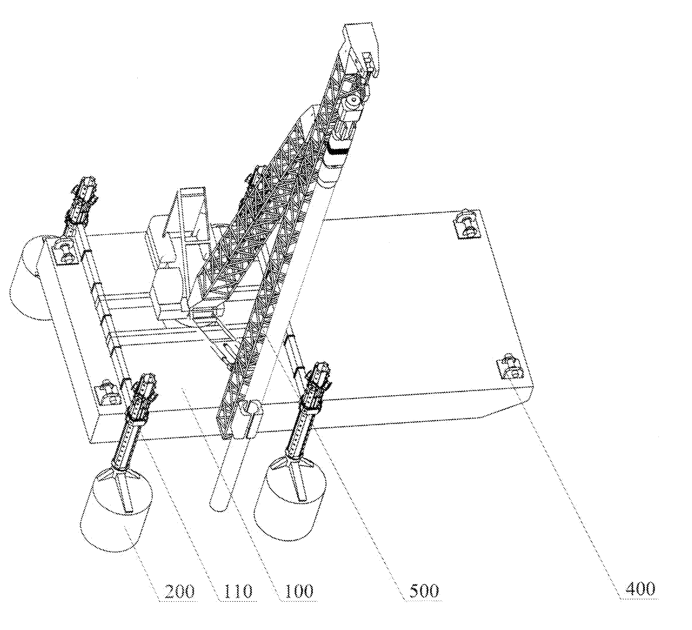
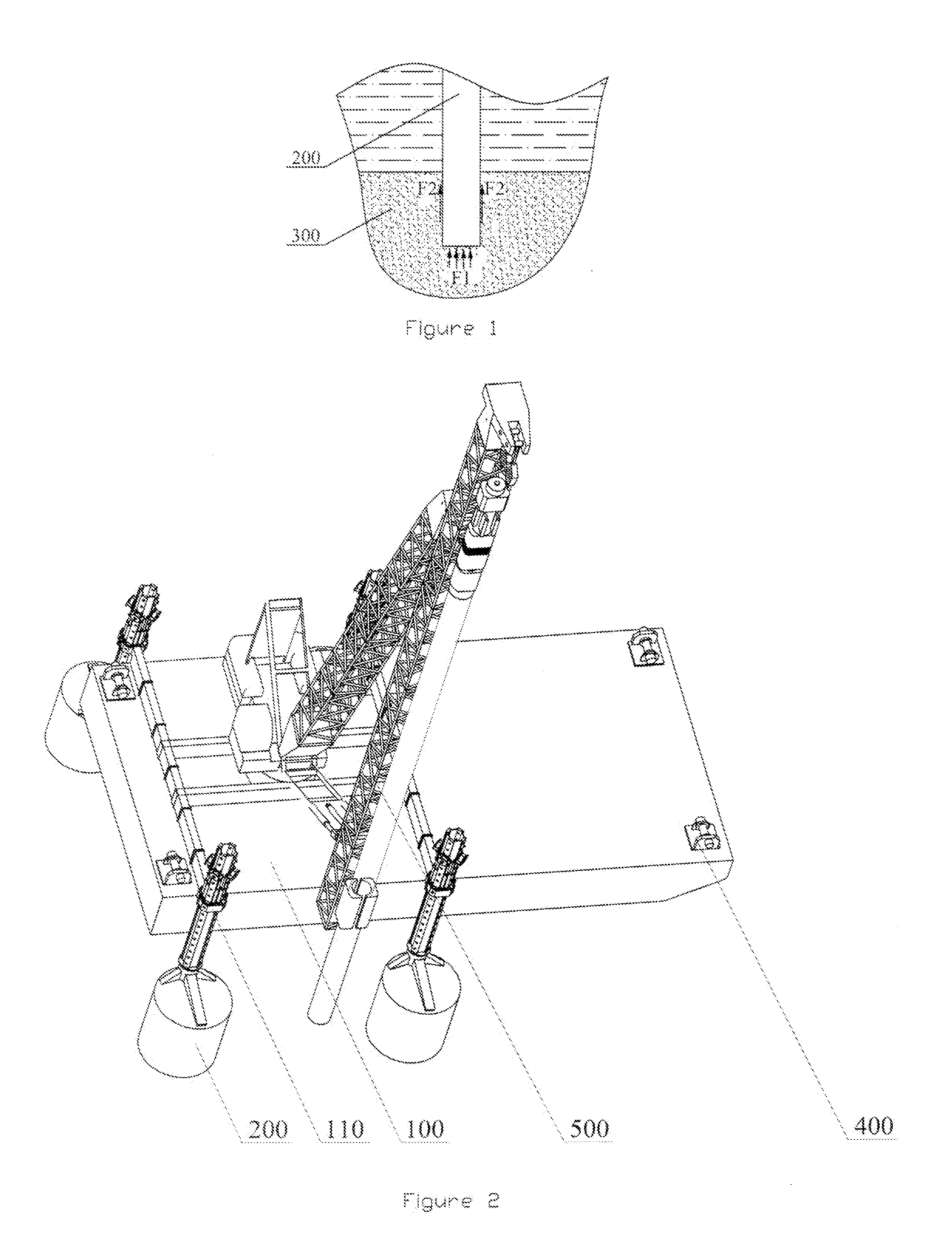
[0058]Reference is made to FIG. 10, which is a side structural schematic view of the piling barge provided by the present invention. The piling device 500 includes a pile frame 510, a hanging hook 520, a boom 530, a turntable 550 and a luffing oil cylinder 540. The turntable 550 is mounted on the hull 100 by means of a turning mechanism, and may be driven to rotate around a vertical axis relative to the hull 100 by a hydraulic motor. One end of the luffi...


PUM


Abstract

A piling barge is disclosed by the present invention. In the piling barge disclosed, a supporting leg includes a supporting arm extended in vertical direction. Differing from the prior art, the supporting leg further includes a supporting base. The supporting base has a transverse section larger than that of the supporting arm, an end of the supporting arm is fixed with the upper surface of the supporting base. The supporting base of the supporting leg having a larger transverse section may receive support from a larger area of mollisol ground and thus provide a larger supporting force for the hull, which enables the piling barge to perform the piling operation on sea areas with mollisol ground. A piling device of the piling barge has pile frame adjusting mechanisms, such as a luffing oil cylinder, a luffing winch mechanism and a turntable, etc., which may adjust the incline angle and the position of the pile frame, therefore the working efficiency of piling operation of the piling barge can be improved.

Description

CROSS-REFERENCE TO RELATED APPLICATIONS[0001]This application claims priority to Chinese Patent Application No. 200910237986.3, filed Nov. 27, 2009, entitled “A Piling Vessel”, which is incorporated by reference herein for all purposes.FIELD OF THE INVENTION[0002]The present invention relates to offshore engineering technology, and in particular, to a piling barge used for offshore piling.THE RELATED ART[0003]Currently, in the exploitation of marine resources, it is necessary to build some functions in a tidal flat (including transfer areas of water and land, such as inland rivers, inland lakes, and marshes) or a neritic zone. For example, wind farms are built in predetermined sea areas to make full use of offshore wind energy. Based on characteristics of offshore engineering operations, particular attention should be paid on basic construction in offshore engineering, so as to provide foundations for subsequent constructions. During the basic construction in a predetermined sea are...

Claims


Application Information

Patent Timeline
Patent Type & Authority Applications(United States)
IPC IPC(8): E02D23/08E02D27/12
CPCB63B21/27B63B38/00E02D13/04E02B2017/0056E02B2017/0078E02B17/021B63B35/00
Inventor WANG, XINMINGZHANG, JIANGU, YANBIN
Owner SANY ELECTRIC CO LTD
Why Eureka
Try Eureka