Example 1
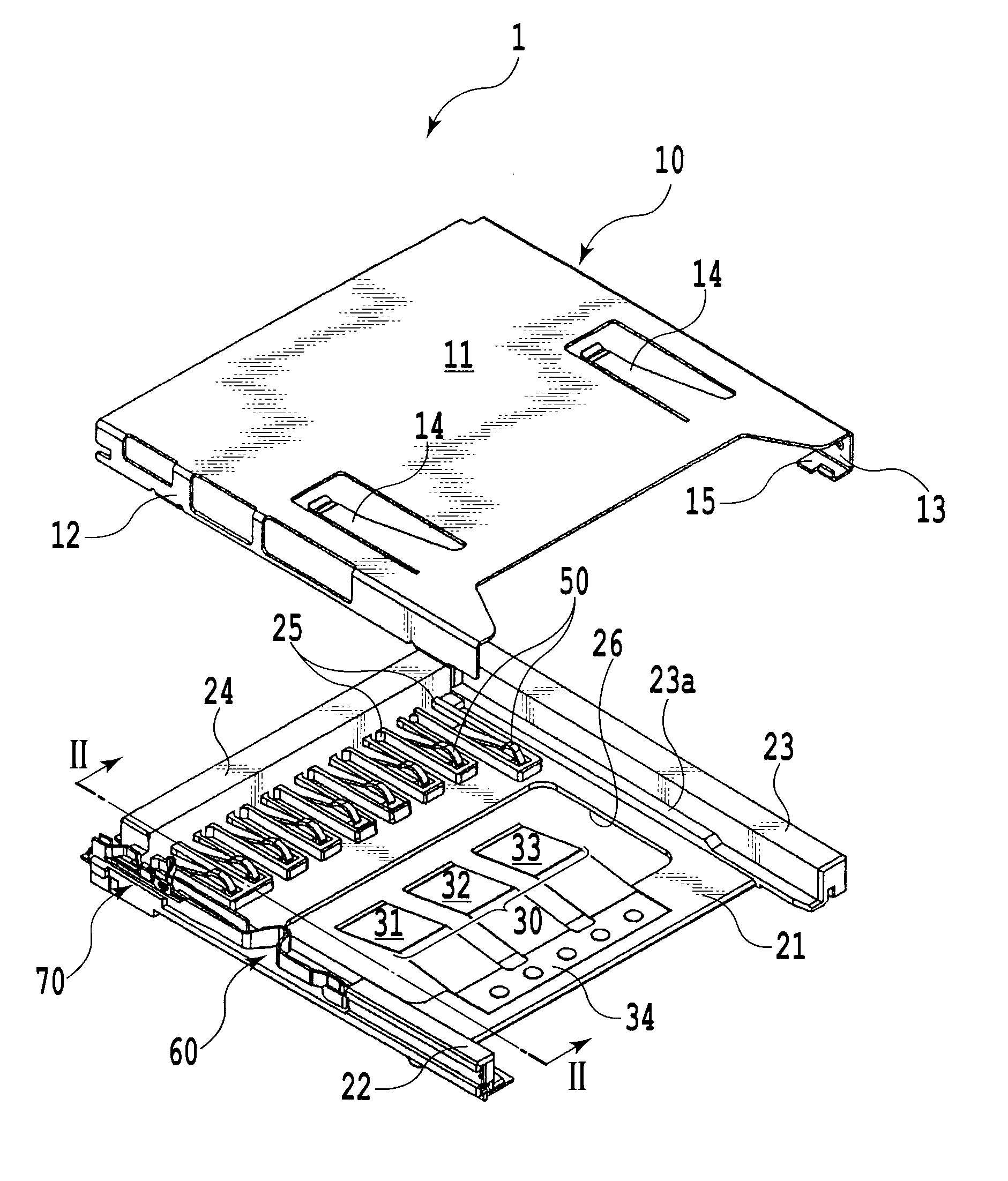
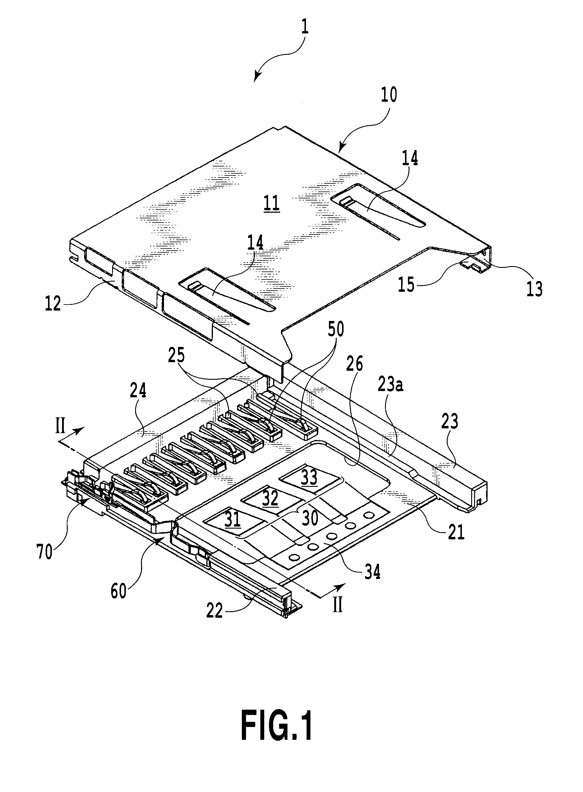
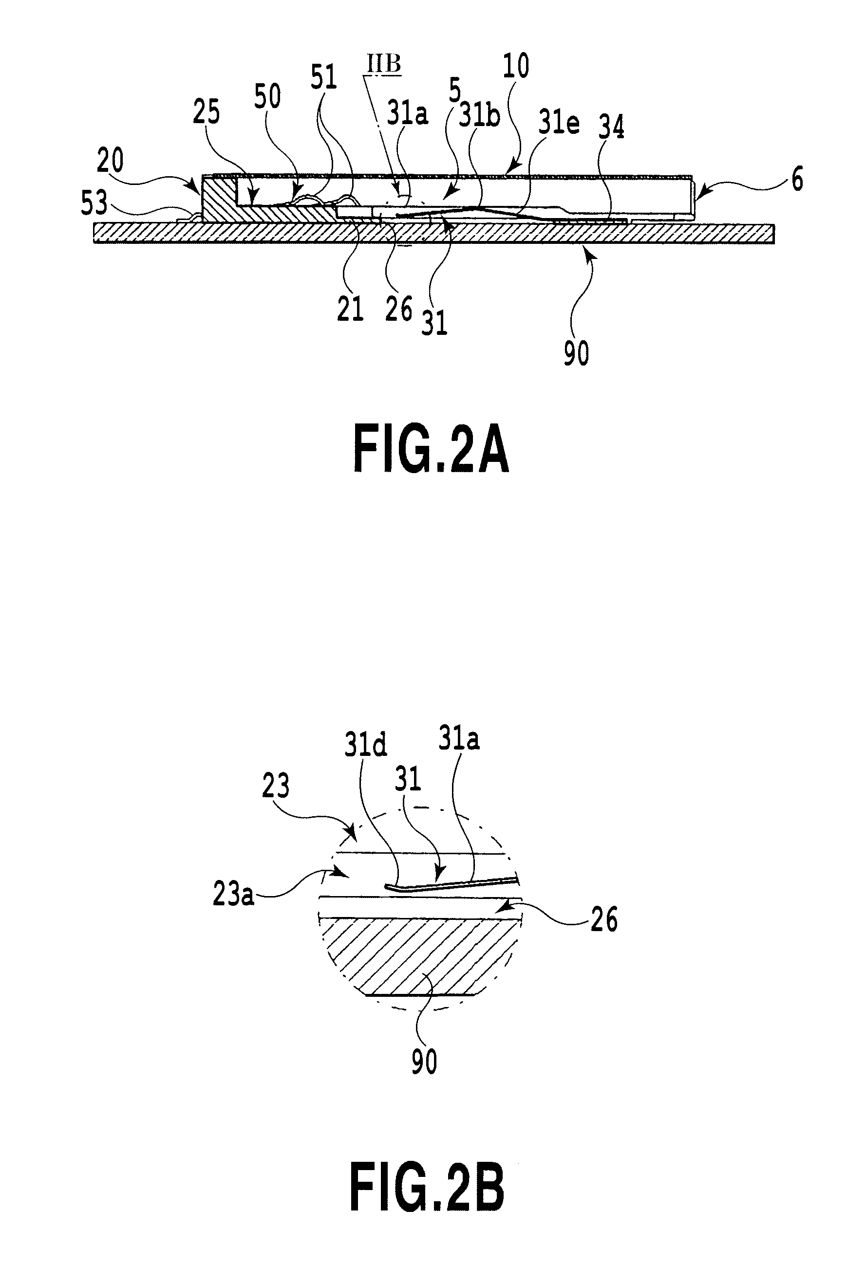
[0028]FIG. 1 is an exploded perspective view of a card connector for small card according to Example 1 of the present invention. FIG. 2A is a schematic cross-sectional view of the card connector for small card of FIG. 1 being fitted onto a printed board of an electronic device or the like, which is taken along a II-II line and shows a state where an IC card is not inserted. FIG. 2B is a partially enlarged cross-sectional view of FIG. 2A. FIG. 3A is a schematic cross-sectional view of the card connector for small card of FIG. 1 as similar to FIG. 2A, which shows a state where the IC card is inserted. FIG. 3B is a partially enlarged cross-sectional view of FIG. 3A as similar to FIG. 2B. FIG. 4A is a perspective view of a modified example of the card connector for small card according to Example 1 of the present invention, which shows the connector in a state where a cover member is detached therefrom. FIG. 4B is a perspective view of another modified example of the card connector for small card according to Example 1 of the present invention, which shows the card connector in the state where the cover member is detached therefrom as similar to FIG. 4A. FIG. 9 is a perspective view of a printed board to which the card connector for small card according to the present invention is attached.
[0029]As shown in FIGS. 2A to 3B, a card connector 1 (hereinafter simply referred to as the “connector”) according to Example 1 of the present invention is fixed by soldering onto a printed board 90 attached to an electronic device as similar to the conventional card connector disclosed in PTL 1. The card connector 1 according to this example connects a small IC card 80, which has been subjected to downsizing and thin profiling, electrically to the printed board 90.
[0030]The card connector 1 according to this example essentially includes a cover member 10, a base member 20, a heat dissipating mechanism 30, and a plurality of contacts 50.
[0031]The cover member 10 is formed of a metal thin plate by press work and defines a card receiving space 5 for receiving at least part of the IC card 80 by being assembled with the base member 20 so as to be vertically stacked on each other (see FIG. 2A). The IC card 80 is inserted from a card insertion slot 6 formed at the back of the card receiving space 5 forward into the card receiving space 5.
[0032]In this example, the cover member 10 is provided with a top board 11, and a right and left pair of side walls 12 and 13, and is formed so as to cover the base member 20. Reference numeral 14 denotes a pair of brake pieces provided so as to prevent the IC card 80 from falling off the connector 1, and reference numeral 15 denotes a pair of fixing pieces provided so as to fix the assembled connector 1 to fixing pads 93 (see FIG. 9) on the printed board 90 by soldering. Here, the cover member 10 may also be provided with a front wall for covering a front wall 24 of the base member 20 at least partially.
[0033]The base member 20 is formed by use of insulative synthetic resin. In this example, the base member 20 includes a bottom wall 21, a right and left pair of side walls 22 and 23, and the front wall 24.
[0034]A plurality of elongated grooves 25 are formed on the front side of the bottom wall 21 of the base member 20 in order to press-fit and fix each of the plurality of contacts 50 to the base member 20. In this example, as shown in FIG. 1, each of the plurality of elongated grooves 25 is formed by surrounding four sides with walls (the front wall 24 of the base member 20 serves as one of the walls). Moreover, the plurality of elongated grooves 25 extend in an anteroposterior direction or a card insertion direction and are formed parallel to one another.
[0035]Therefore, the plurality of contacts 50 are disposed parallel to one another. Each of the plurality of contacts 50 is fixed and supported inside the groove 25 in a cantilever fashion such that a contact point 51 thereof can contact an external contact point of the IC card 80 which is inserted into the card receiving space 5. Each contact point 51 of the contact 50 is elastically deformable in a vertical direction and is thereby capable of electrically contacting the external contact point of the IC card 80 to be inserted at a predetermined contact pressure. Each of the plurality of contacts 50 is also supported inside the elongated groove 25 such that a terminal portion 53 connected by soldering to an external contact point 91 (see FIG. 9) of the printed board 90 passes through the front wall 24 of the base member 20 and protrudes forward. Here, the fixation of each of the plurality of contacts 50 to the base member 20 is not limited only to the above-described configuration in which the elongated grooves are provided.
[0036]A window portion 26 serving as a rectangular cutoff portion is provided at a central portion of the bottom wall 21 of the base member 20. The rectangular window portion 26 is formed so as to penetrate the bottom wall 21. Heat dissipating pieces 31, 32, and 33 constituting a heat dissipating mechanism 30 to be described later 30 are disposed in the window portion 26.
[0037]A pair of guide rails (only a guide rail 23a on a right side is shown in FIG. 1) for guiding the IC card 80 when inserting and pulling out the IC card 80 are formed inside the respective right and left side walls 22 and 23, at the inner corner portions intersecting with the bottom wall 21. The guide rails extend in the anteroposterior direction or the card insertion direction.
[0038]In this example, a write protect switch 60 for detecting a position of a write protect button (not shown) of the IC card 80 to be loaded and a card recognition switch 70 for detecting complete insertion of the IC card 80 into the card receiving space 5 of the card connector 1 are provided on the left side wall 22. Moreover, although not provided in this example, it is also possible to provide an ejection mechanism such as a conventional well-known push-push ejection mechanism for facilitating insertion and ejection of the IC card 80 along the right side wall 23, for example. If the ejection mechanism is provided, the heat dissipating mechanism 30 can also be used as a brake piece for preventing fall-out when ejecting the card.
[0039]Next, the heat dissipating mechanism 30 characterizing the present invention will be described. As described previously, the heat dissipating mechanism 30 is disposed in the window portion 26 formed on the base member 20. The heat dissipating mechanism 30 is integrally formed of a heat conductive metal thin plate by press work. In this example the heat dissipating mechanism 30 includes, without limitation, the plurality of heat dissipating pieces 31, 32, and 33 and a coupling piece 34 configured to couple an end of each of these heat dissipating pieces 31, 32, and 33 with one another and thereby to integrate the plurality of heat dissipating pieces 31, 32, and 33. The coupling piece 34 is the elongated and flat plate member that extends in a right-to-left direction or an orthogonal direction to the card insertion direction. The coupling piece 34 may be formed separately from the heat dissipating pieces 31, 32, and 33 or may be integrally formed as in this example. Alternatively, it is also possible to omit the coupling piece 34.
[0040]The heat dissipating pieces 31, 32, and 33 have the same strip shape when viewed from above, extend in the anteroposterior direction or the card insertion direction, and are disposed parallel to one another. The shape of the heat dissipating pieces 31, 32, and 33 will be explained by use of the heat dissipating piece 31 as an example. As shown in FIG. 2A, the heat dissipating piece 31 includes a front heat dissipating piece 31a, a bent portion 31b, and a rear heat dissipating piece 31c, and is formed into an angle shape protruding upward in terms of a cross section. By forming the angle shape as described above, the heat dissipating piece 31 is elastically deformable so as to be flattened when the IC card 80 is inserted into the card insertion space 5.
[0041]A front end portion 31d of the front heat dissipating piece 31a of the heat dissipating piece 31 is a member configured to contact a heat dissipating pad 92 provided on the printed bard 90 when inserting the IC card 80 into the card receiving space 5, and is formed as a free end. As shown in FIG. 2B, the front end portion 31d of the front heat dissipating piece 31a is preferably rolled back to form an arc shape protruding downward. By forming the front end portion 31d into the roll-back structure as described above, the front end portion 31d can smoothly contact the heat dissipating pad 92 provided on the printed board 90. Meanwhile, it is also possible to further provide a flat portion in the front end portion 31d in order to increase a contact area with the heat dissipating pad 92 provided on the printed board 90 to improve a heat dissipation effect.
[0042]The bent portion 31b of the heat dissipating piece 31 is formed substantially at a central part in the anteroposterior direction of the heat dissipating piece 31 and to extend orthogonally to the card insertion direction. As shown in FIG. 2A, the bent portion 31b is formed so as to protrude upward from an upper surface of the bottom wall 21 into the card receiving space 5 when the IC card 80 is not inserted into the card receiving space 5. The shape of the bent portion 31b in this example is formed by bending so as to protrude upward while defining an obtuse angle to establish a line contact with the IC card 80 to be inserted. However, the shape is not limited only to the foregoing. The bent portion 31b may be bent upward so as to be curved into an arc shape or may be bent so as to define a flat portion as shown in Example 2 to be described later in order to increase the contact area with the IC card 80 to improve the heat dissipation effect.
[0043]The rear heat dissipating piece 31c of the heat dissipating piece 31 has substantially the same length as the front heat dissipating piece 31a and a rear end portion thereof is coupled with the coupling piece 34. In this example, the plurality of heat dissipating pieces 31, 32, and 33 are fixed to the upper surface of the bottom wall 21 of the base member 20 via the coupling piece 34 by heat sealing. While the coupling piece 34 functions as a fixing member to the bottom wall 21, the coupling piece 34 also functions as a heat dissipating member to transfer the heat to the bottom wall 21. When the coupling piece 34 is omitted, the multiple heat dissipating pieces 31, 32, and 33 are individually fixed to the bottom wall 21. In this case, it is preferable to provide a flat extension piece at the back of the rear heat dissipating piece 31 of the heat dissipating piece 31 as a fixing member for the heat dissipating piece 31.
[0044]Note that the fixation of the multiple heat dissipating pieces 31, 32, and 33 to the bottom wall 21 of the base member 20 is not limited only to the above-described mode. For example, the heat dissipating piece 31 may be fixed to a lower surface of the bottom wall 21 of the base member 20 via the coupling piece 34 if such a configuration is acceptable in terms of design. Meanwhile, it is possible to fix the heat dissipating pieces by insert molding so as to be buried into the bottom wall 21 via the coupling piece 34 as shown in FIG. 4A, or it is also possible to form a slit on the bottom wall 21 and to press-fit and fix the heat dissipating pieces to the bottom wall 21 via the slit as shown in FIG. 4B.
[0045]As described above, the heat dissipating mechanism 30 is formed of the plurality of heat dissipating pieces 31, 32, and 33 and is therefore more flexible than the case of being formed as a single heat dissipating piece. Accordingly, it is possible to reduce a force necessary for inserting the card and to achieve smooth attaching and detaching operations of the card. Moreover, if the card is warped, the heat dissipating pieces 31, 32, and 33 each can evenly contact the card and dissipate the heat reliably. Hence there is not a risk of degrading heat dissipation efficiency.
[0046]As described previously, the plurality of contacts 50 are the members configured to connect the inserted IC card 80 electrically to the printed board 90 and are disposed parallel to one another on the front side of the bottom wall 21 of the base member 20. As shown in FIG. 2A, each of the contacts 50 includes the contact point 51 which contacts the external contact point (not shown) of the IC card 80, and the terminal portion 53 which contacts the external contact point 91 of the printed board 90. Moreover, the contacts 50 are respectively supported in the cantilever fashion inside the elongated grooves 25 provided on the bottom wall 21 of the base member 20 so that the contact portion 51 can elastically contact the external contact point of the IC card 80. Therefore, the contact point 51 of each contact 50 is supported by the base member 20 so as to protrude into the card receiving space 5.
[0047]The card connector 1 as Example 1 of the present invention has been described above. Now, an operation of the card connector will be described below by using FIGS. 2A and 2B as well as FIGS. 3A and 3B, focusing particularly on the heat dissipating piece 31 constituting the heat dissipating mechanism 30.
[0048]FIG. 2A shows a state where the IC card 80 is not inserted into the card receiving space 5. At this time, the bent portion 31b of the heat dissipating piece 31 of the heat dissipating mechanism 30, one end of which is fixed to the bottom wall 21 of the member 20 via the coupling piece 34, protrudes from the upper surface of the bottom wall 21 of the base member 20 into the card receiving space 5 located thereabove. In this example, as shown in FIG. 2B, the front end portion 31d being the free end of the heat dissipating piece 31 is disposed above and apart from the printed board 90. However, the layout of the front end portion 31d is not limited only to the foregoing and the front end portion 31d may also be disposed so as to contact (the heat dissipating pad 92 of) the printed board 90. Meanwhile, the contact portion 51 of the contact 50 also protrudes from the groove 25 into the card receiving space 5 located thereabove.
[0049]In the state shown in FIG. 2A, when the IC card 80 is inserted from the card insertion slot 6, the bent portion 31b of the heat dissipating piece 31 of the heat dissipating mechanism 30 contacts either a tip end surface 81 or a step portion 83 of the IC card 80. Accordingly, the front end portion 31d of the heat dissipating piece 31 is pushed downward and thereby contacts the upper surface of the printed board 90.
[0050]When the IC card 80 is further inserted and the tip end surface 81 of the IC card 80 reaches a rear surface of the front wall 24 of the base member 20, the bent portion 31b of the heat dissipating piece 31 contacts a bottom surface 82 of the IC card 80. Therefore, as shown in FIG. 3A, the heat dissipating piece 31 which is formed into the angle shape protruding upward extends inside the window portion 26 of the bottom wall 21 in the flattened fashion. At this time, the front end portion 31d of the heat dissipating piece 31 contacts the heat dissipating pad 92 provided on the printed board 90 (see FIG. 3B). Here, it is needless to say that the length of the front end portion 31d in the anteroposterior direction of the heat dissipating piece 31 is adjusted properly so as not to touch the window portion 26 of the bottom wall 21.
[0051]In the state shown in FIG. 3A, signals are transmitted and received between the IC card 80 and the printed board 90. Here, the heat accumulated on the IC card 80 flows toward the printed board 90 having a large heat capacity via the respective front end portions of the multiple heat dissipating pieces 31, 32, and 33 as well as the coupling piece 34 which constitute the heat dissipating mechanism 30.
[0052]Meanwhile, in the state shown in FIG. 3A, the plurality of heat dissipating pieces 31, 32, and 33 are elastically deformed into the flattened shape, whereby the IC card 80 is pressed against the top board 11 of the cover member 10 by resilience thereof. Accordingly, the position in the vertical direction of the IC card 80 is fixed. Hence it is expected to obtain predetermined contact pressures with the multiple contacts 50. Moreover, it is also expected to achieve heat dissipation via the metallic cover member 10.