Bill handling apparatus

a technology for handling equipment and bill boxes, applied in the direction of thin material handling, sorting, instruments, etc., can solve the problems of increasing the complexity of the one-way conveying path, and the decrease of the size of the bill storage box relative to the size of the entire apparatus, so as to simplify the bill conveying mechanism and reduce the entire length of the conveying path

Active Publication Date: 2011-06-02
HITACHI CHANNEL SOLUTIONS CORP
View PDF5 Cites 14 Cited by
  • Summary
  • Abstract
  • Description
  • Claims
  • Application Information

AI Technical Summary

Benefits of technology

[0018]According to the present invention, it is possible to reduce the entire length of the bill conveying path and simplify the bill conveying mechanism.

Problems solved by technology

The conveying path of the one-way conveying path will be complicated.
Therefore, there are disadvantages that the volume of structure forming the conveying path increases relative to the entire apparatus and the size of the bill storage box decreases relative to the size of the entire apparatus.
Therefore, failure in stacking the bills may be caused in the bills in the recycle box and problems in conveyance, such as jam, may be generated in feeding bills from the recycle box at the next time.
However, the apparatus disclosed in JP-A-2009-110230 requires an exclusive conveying path 56 for conveying bills from the loading box to the bill discriminating unit, which make the conveying path complicated.
Further, in this configuration, it is required to implement a three-story conveying path composed of two two-way conveying paths 51b and 58 and one one-way conveying path 55 between the bottom of the temporary storage unit and the top of the recycle box, such that it is difficult to reduce the height of the apparatus, and both achieve a compact apparatus and increase the capacity of the recycle box.

Method used


Image

  • Bill handling apparatus
  • Bill handling apparatus
  • Bill handling apparatus

Examples


Embodiment Construction

[0038]Hereinafter, an embodiment of the present invention is described with reference to the accompanying drawings.

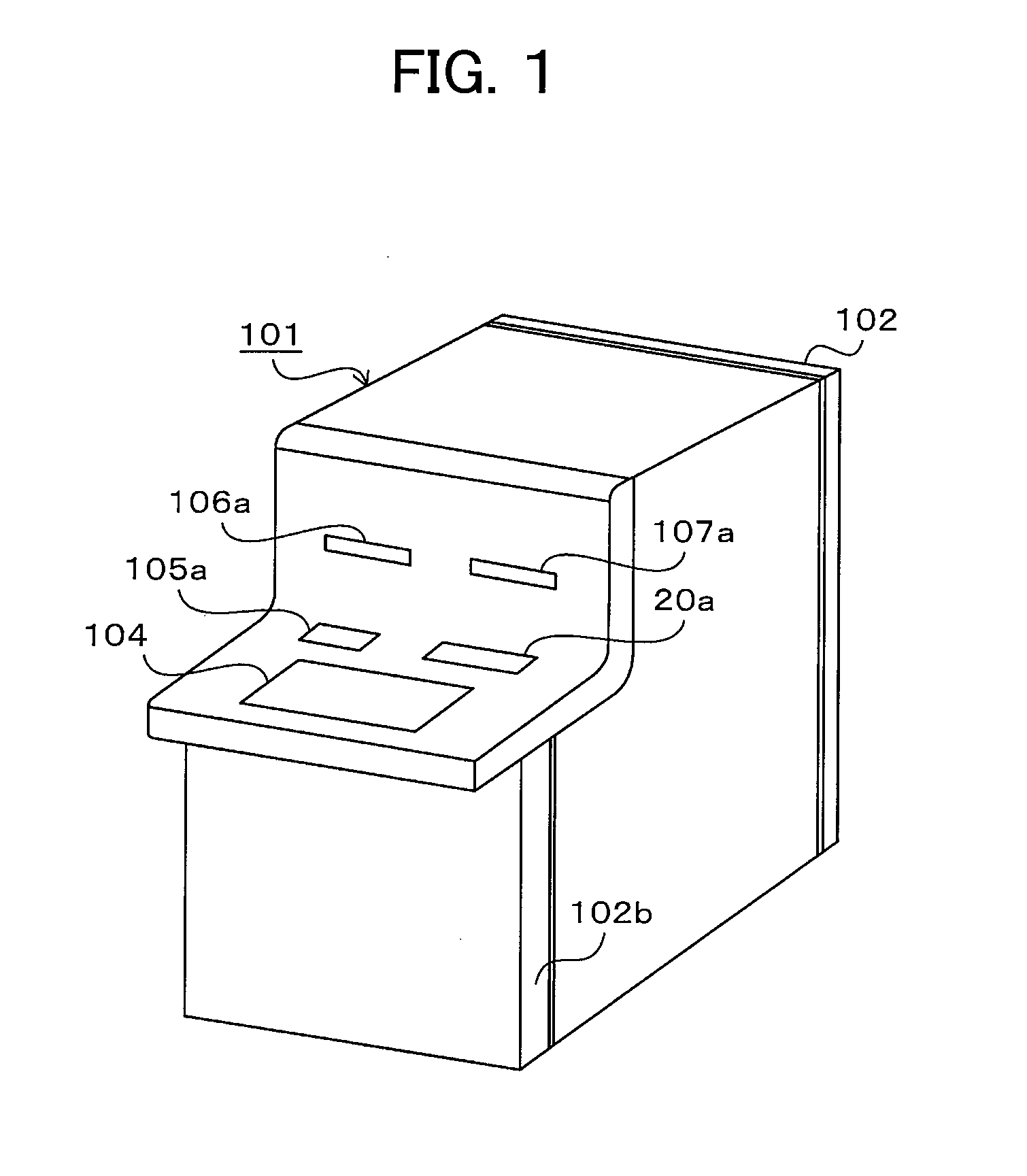
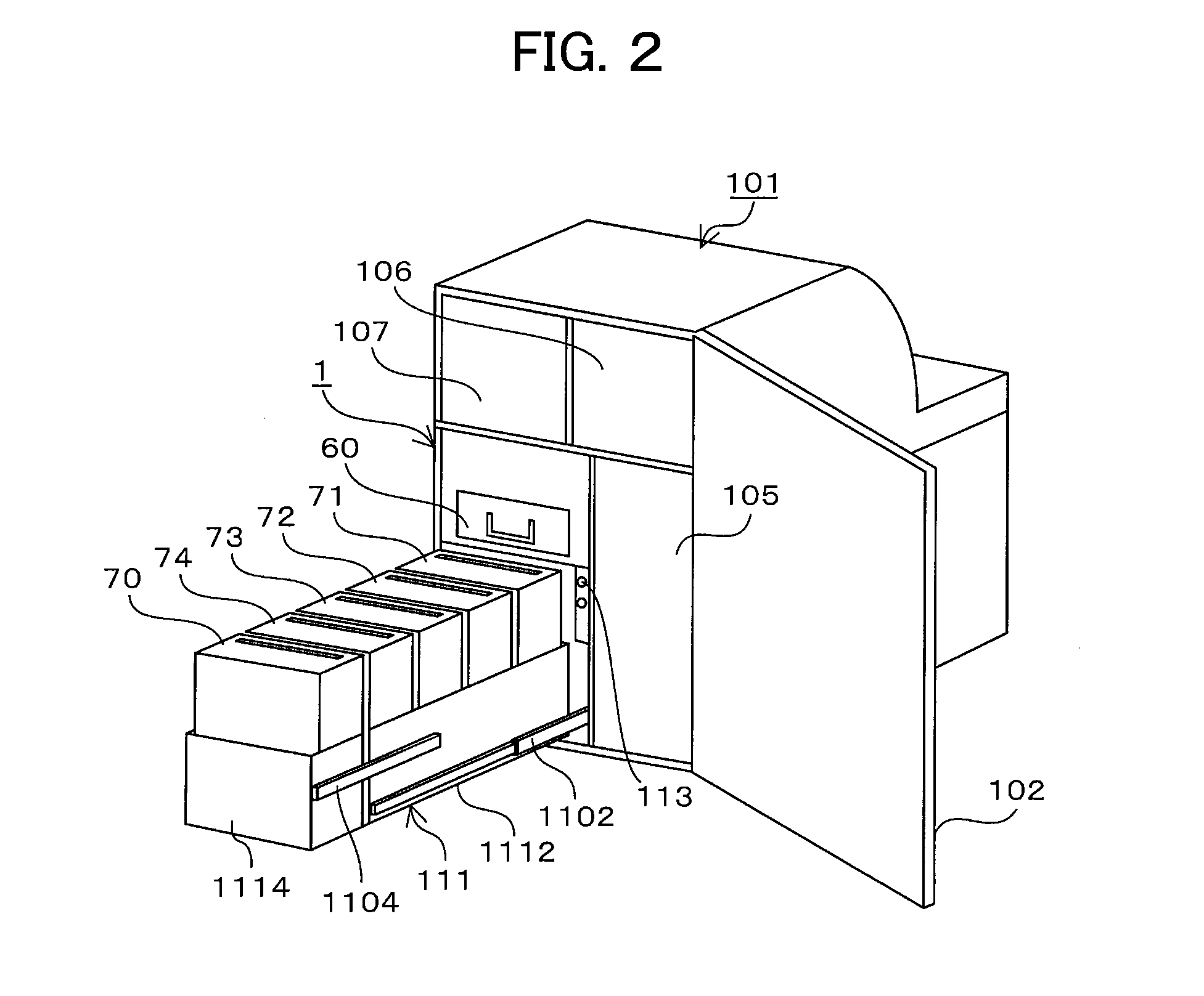
[0039]FIG. 1 is a view showing the external appearance of an ATM equipped with a bill handling apparatus and FIG. 2 is a view showing the rear side of the bill handling apparatus.

[0040]The ATM 101 uses a card, bills, and a detailed statement as transaction media and performs processes, such as deposit, payment, and transfer by operation of users. A bankbook processing mechanism 106 that processes a user's bankbook and prints and discharges a transaction detailed statement and a card and statement processing mechanism 107 that processes a user's cards and prints and discharges a transaction detailed statement are provided at the upper part of the ATM 101. The bankbook processing mechanism 106 processes a user's bankbook inserted through a slot 106a, and prints and discharges a transaction detailed statement. The card and statement processing mechanism 107 processes a use...


PUM


Abstract

A bill handling apparatus includes: a first loop-like conveying path that includes a bill discriminating unit, is connected to a bill receiving and dispensing port and a temporary storage unit, and connected to a plurality of loading boxes to convey bills in two directions; a second conveying path connected to the loading box to convey bills in two directions; a first gate that connects the first conveying path with the second conveying path and switches a conveying direction of the conveying path that conveys bills; and a controller that controls switching of the first gate and conveyance of the conveying path. The controller controls the bills conveyed to the first conveying path in one of the two directions to be conveyed to the loading box through the second conveying path via the first gate, and the bills conveyed from the loading box through the second conveying path to be conveyed to the first conveying path in one of the two directions via the first gate.

Description

CLAIM OF PRIORITY[0001]The present application claims priority from Japanese application JP 2009-267081 filed on Nov. 25, 2009, the content of which is hereby incorporated by reference into this application.FIELD OF THE INVENTION[0002]The present invention relates to a bill handling apparatus that is mounted on and used in ATMs (Automatic Teller Machine) automatically receiving and dispensing bills by operation of users.BACKGROUND OF THE INVENTION[0003]Recently, according to an increase in kinds of denomination values and an increase in storage capacity of bills that ATMs handle, bill handling apparatuses equipped with as many large bill boxes as possible have been proposed. For example, JP-A-H8 (1996)-221636 and JP-A-2009-110230 disclose bill handling apparatuses in which a plurality of bill boxes is arranged side by side at the lower part of the apparatus and the other components are collectively arranged in the upper part of the apparatus.[0004]In the bill handling apparatus disc...

Claims


Application Information

Patent Timeline
Patent Type & Authority Applications(United States)
IPC IPC(8): G06F7/00B07C5/00
CPCG07D11/0081G07F9/10G07F7/04G07D11/40G07D11/22B65H31/24
Inventor AOJI, HIROKAZUMIZUNO, SHOSEGUCHI, MASAHIROTANAKA, SHUUJIKANAGAWA, TAKESHIYASUEDA, TORU
Owner HITACHI CHANNEL SOLUTIONS CORP
Why Eureka
Try Eureka