Compressor discharge control on a transport refrigeration system

a refrigeration system and compressor technology, applied in refrigeration machines, lighting and heating apparatus, refrigeration safety arrangements, etc., can solve the problems of high compressor discharge temperature, refrigeration systems that operate, and high compression ratios that require additional compression temperature controls

Active Publication Date: 2011-06-09
CARRIER CORP
View PDF28 Cites 39 Cited by
  • Summary
  • Abstract
  • Description
  • Claims
  • Application Information

AI Technical Summary

Benefits of technology

[0009]A stable system and process is provided to control the de

Problems solved by technology

When suction modulation occurs at high ambient temperatures, the refrigerant supplied to the compressor may be too hot, absent some correcting measures, resulting in compressor discharge temperatures that are too high.
Further, refrigeration systems that operate at low suction density and low mass flow conditions coupled with high compression ratios require additional compression temperature controls.
In other refrigeration systems, such as mobile container systems used in tropical climates, a high ambient temperature adversely affects the temperature of the refrigerant, particularly the compressor discharge temperature.
If discharge temperatures are not prevented from getting too hot, the compressor lubricant can break down and ultimately cause failure of the compressor.
Unfortunately, refrigeration systems utilizing a quench valve have increased complexity, which increases cost.
The increased complexity also makes system packaging more difficult in the confined space of a transport refrigeration system.
Another drawback of systems utilizing a quench valve is that the liquid refrigerant bypasses the evaporator, thereby decreasing system efficiency.
Also, the compressor superheat is more difficult to control with the use of a solenoid valve because large slugs of liquid are dumped into the suction inlet of the compressor.
Too much liquid refrigerant can also result in floodback to the compressor and can ultimately cause failure of the compressor.

Method used


Image

  • Compressor discharge control on a transport refrigeration system
  • Compressor discharge control on a transport refrigeration system
  • Compressor discharge control on a transport refrigeration system

Examples


Embodiment Construction

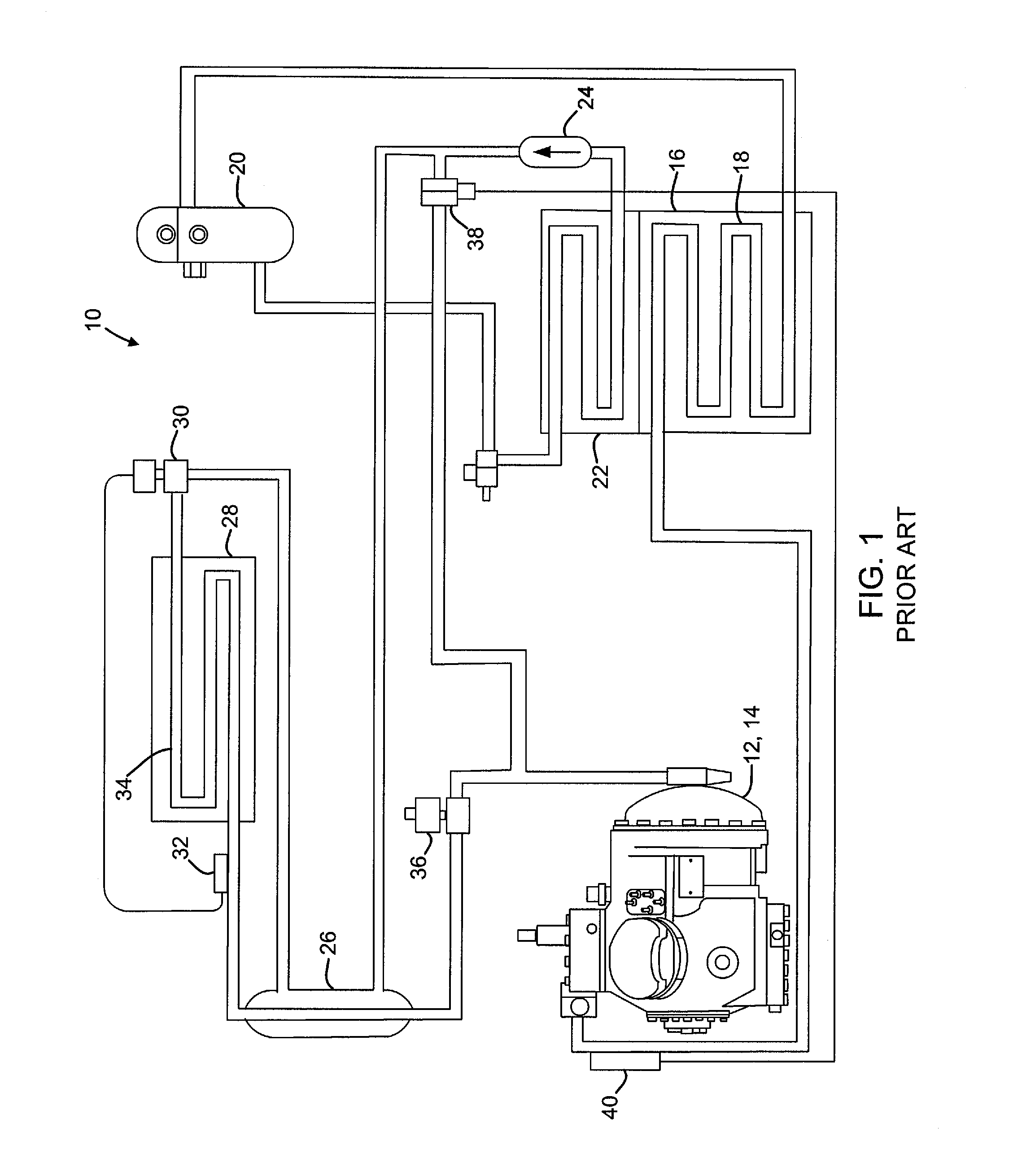
[0018]FIG. 1 shows a schematic representation of an exemplary embodiment of a refrigerant vapor compression system 10, such as a conventional prior art transportation refrigeration system. Such a system 10 typically includes a compressor 12, such as a reciprocating compressor, which is driven by a motor 14 to compress refrigerant. In the compressor, the refrigerant is compressed to a higher temperature and pressure. The refrigerant then moves to a condenser 16, which may be an air-cooled condenser. The condenser 16 includes a plurality of condenser coil fins and tubes 18, which receives air, typically blown by a condenser fan (not shown). By removing latent heat through this step, the refrigerant condenses to a high pressure / high temperature liquid and flows to a receiver 20 that provides storage for excess liquid refrigerant during low temperature operation. From the receiver 20, the refrigerant flows through subcooler unit 22, then to a filter-drier 24 which keeps the refrigerant ...


PUM


Abstract

In a refrigeration system having a compressor, a condenser, an evaporator, and a controller for controlling an expansion valve, a process for controlling compressor discharge during a cooling cycle comprising the steps of monitoring a compressor discharge parameter, comparing the compressor discharge parameter to a set point stored in a controller memory, and selectively operating the expansion valve upstream of the evaporator in response to a difference between the compressor discharge parameter and the set point.

Description

CROSS-REFERENCE TO RELATED APPLICATION[0001]Reference is made to and this application claims priority from and the benefit of U.S. Provisional Application Ser. No. 61 / 100,445, filed Sep. 26, 2008, entitled “COMPRESSOR DISCHARGE CONTROL ON A TRANSPORT REFRIGERATION SYSTEM”, which application is incorporated herein in its entirety by reference.FIELD OF THE INVENTION[0002]This disclosure relates generally to transport refrigeration units and, more specifically, to controlling compressor discharge superheat without a quench valve.BACKGROUND OF THE INVENTION[0003]A transport refrigeration system used to control enclosed areas, such as the insulated box used on trucks, trailers, containers, or similar intermodal units, functions by absorbing heat from the enclosed area and releasing heat outside of the box into the environment. The transport refrigeration system commonly includes a compressor to pressurize refrigerant vapor, and a condenser to cool the pressurized vapor from the compresso...

Claims


Application Information

Patent Timeline
IPC IPC(8): F25B1/00F25B41/04
CPCF25B49/027F25B2600/2513F25B2700/21172F25B2700/2106F25B2700/21152
Inventor WEYNA, PAUL V.DUDLEY, ELIOT W.ABBOTT, ALAN D.SENF, JR., RAYMOND L.
Owner CARRIER CORP
Why Eureka
Try Eureka