Sprocket with damper and compensator

a technology of compensator and damper, which is applied in the direction of mechanical equipment, gearing details, hoisting equipment, etc., can solve the problem that current dampers with rubber cannot withstand the hot oil environment for the life of the vehicl

Inactive Publication Date: 2011-06-09
BORGWARNER INC
View PDF18 Cites 4 Cited by
  • Summary
  • Abstract
  • Description
  • Claims
  • Application Information

AI Technical Summary

Benefits of technology

[0005]A sprocket unit mounted to a shaft comprising a damper with recesses and chambers for receiving spring loaded weights; a sprocket mounted adjacent to the damper having a hub defining at least one aperture and at least one slot having a length; a front end plate mounted on the first shaft adjacent to the sprocket with a hub defining an apertures aligned with the apertures of the sprocket; and springs received within the apertures of the sprocket, the apertures of the front end plate, and the recesses of the damper. When the shaft rotates and the firing frequency of the engine is in tune with the resonant frequency of the first shaft, the spring loaded weights slide in the chambers of the damper to dampen out resonant frequency in the first shaft. The torsional load of the first shaft on the second shaft is decreased by the sprocket rotating an amount no greater than the length of the slot and the spring received within the damper, sprocket, and end plate extends and compresses, reducing the torsional load to the second shaft from the first shaft.

Problems solved by technology

Current dampers with rubber will not withstand the hot oil environment for the life of the vehicle.

Method used


Image

  • Sprocket with damper and compensator
  • Sprocket with damper and compensator
  • Sprocket with damper and compensator

Examples


Embodiment Construction

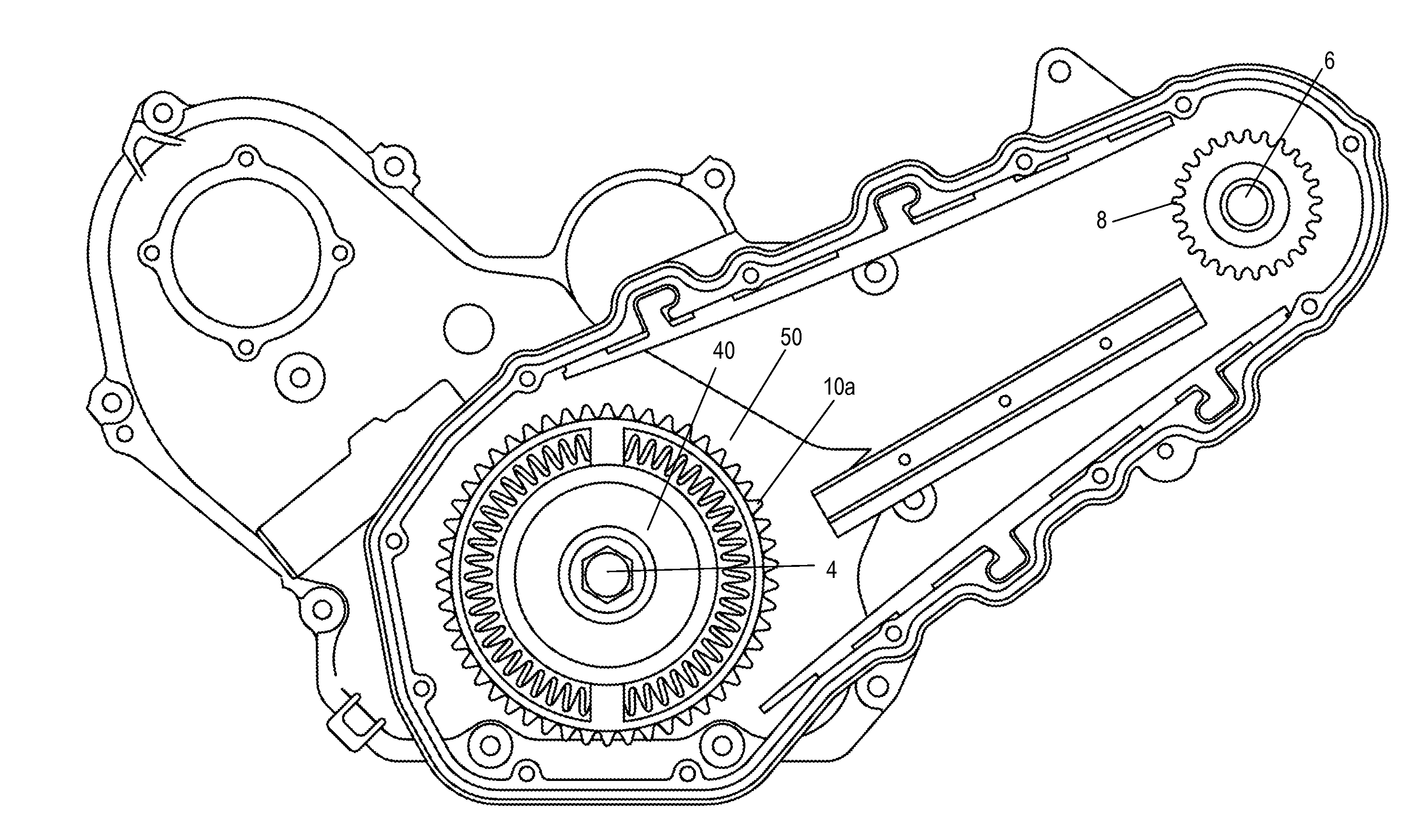
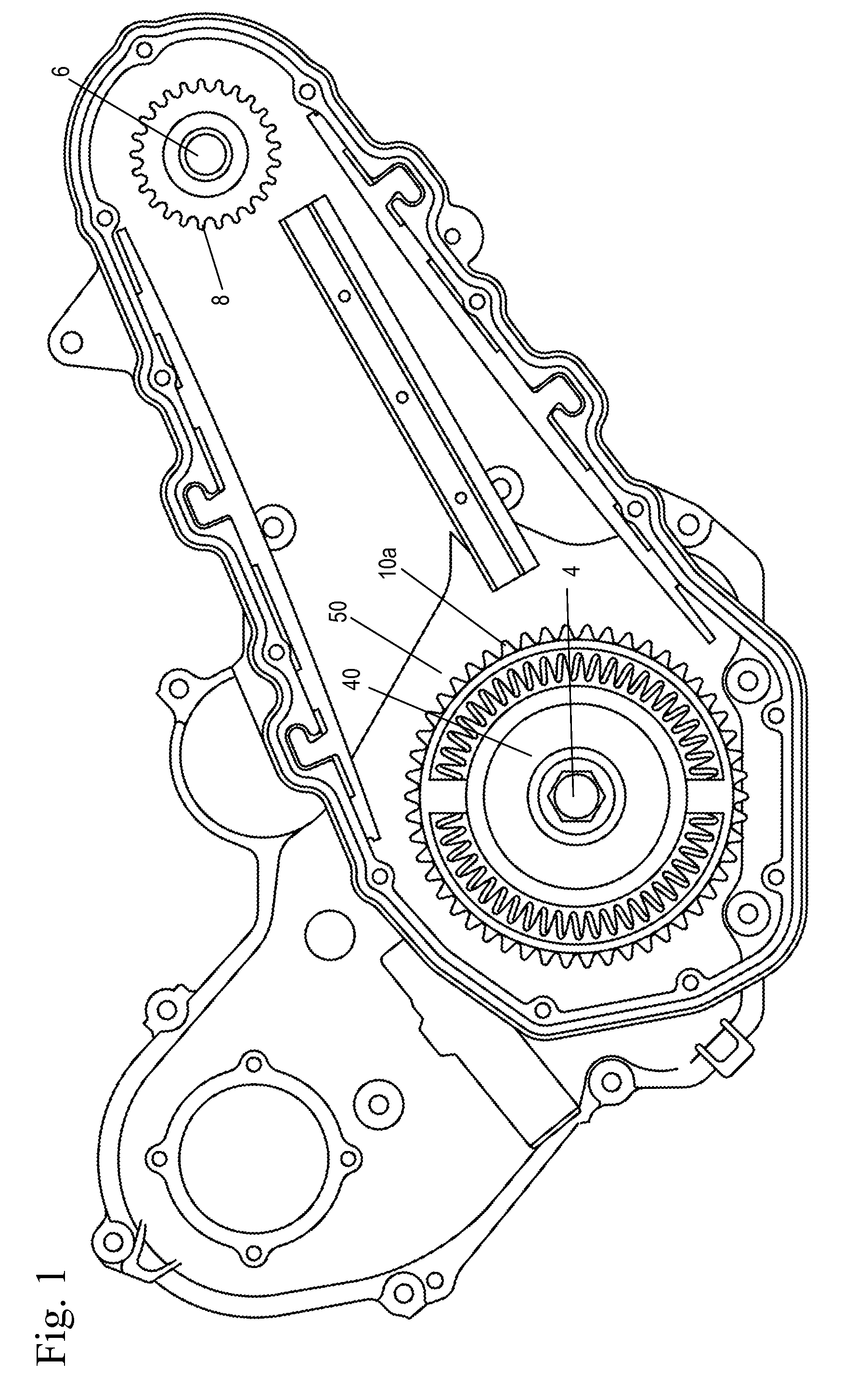
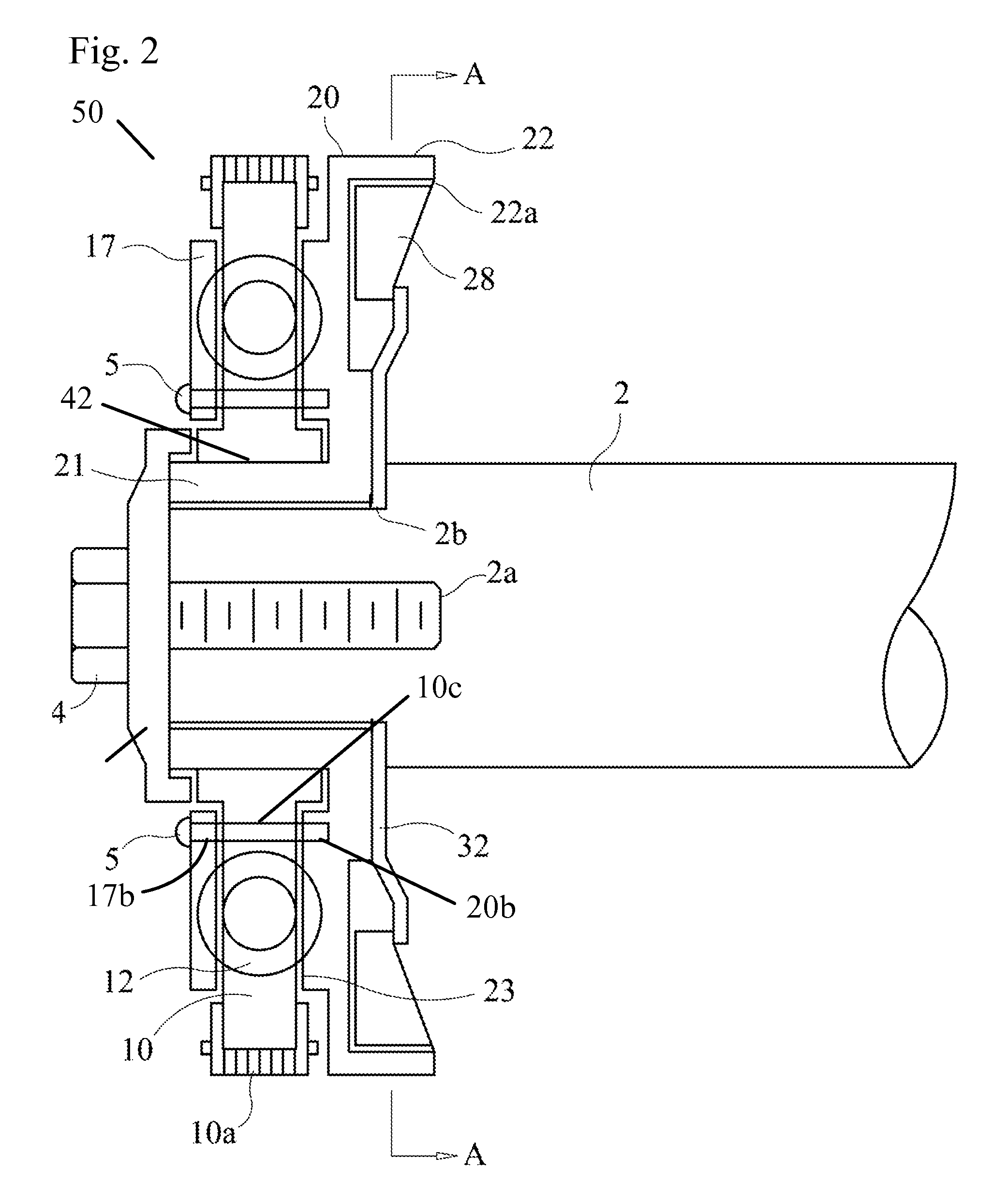
[0011]The sprocket unit 50 of the present invention includes a compensator and a damper mounted together as a single unit on a first shaft. The compensator reduces torsional load of the first shaft relative to the second shaft and the damper dampens the vibrations and twisting motion of the first shaft when the resonance of the firing frequency of the engine coincides with the resonance of the first shaft. The damper of the sprocket unit 50 of the present invention is able to run in a hot oil environment for the life of the vehicle. The sprocket unit 50 may be mounted to a drive shaft of a driven shaft. The chain drive or belt in which the sprocket of the sprocket unit 50 engages may be used to drive many devices in the engine, including but not limited to a camshaft, electric motor, or balance shaft system.

[0012]FIGS. 1-5 show the sprocket unit 50 of the present invention. It should be noted that in FIG. 1 the chain lid has been removed from the figure for clarity. The sprocket uni...


PUM


Abstract

A sprocket unit comprising: a damper mounted on the first shaft with a first face defining a recess and a second face defining chambers for receiving spring loaded weights; a sprocket mounted to the first shaft with a hub defining an aperture and a slot; a front end plate mounted on the shaft with a hub defining an aperture aligned with the aperture of the sprocket; and a spring received within the aperture of the sprocket, the aperture of the front end plate, and the recess of the damper. When the first shaft rotates and firing frequency of the engine coincides with a resonant frequency of the first shaft, the spring loaded weights slide in the chambers of the damper, dampening out the resonant frequency in the first shaft and when the sprocket rotates the spring compresses and extends, reducing torsional load of the first shaft on the second shaft.

Description

BACKGROUND OF THE INVENTION[0001]1. Field of the Invention[0002]The invention pertains to the field of sprockets. More particularly, the invention pertains to a sprocket with a damper and a compensator.[0003]2. Description of Related Art[0004]As modern vehicles and engine compartments become smaller, the requirement to have more compact engines becomes greater. One way to achieve this is to put the crankshaft damper inside the timing drive cover. Since this is an environment that is subjected to oil conditions, a damper must be able to tolerate these extreme conditions. Current dampers with rubber will not withstand the hot oil environment for the life of the vehicle. Also, as the electrification of accessories becomes common place, the need for the crankshaft to extend out of the engine is minimized.SUMMARY OF THE INVENTION[0005]A sprocket unit mounted to a shaft comprising a damper with recesses and chambers for receiving spring loaded weights; a sprocket mounted adjacent to the d...

Claims


Application Information

Patent Timeline
Patent Type & Authority Applications(United States)
IPC IPC(8): F16H55/14
CPCF16F15/1421Y10T74/19898F16H2055/306Y10T74/1884Y10T74/19633F16H55/30
Inventor SIMPSON, ROGER T.
Owner BORGWARNER INC
Why Eureka
Try Eureka