Pontoon planer

Inactive Publication Date: 2011-06-09
WILSON KEITH V
View PDF9 Cites 4 Cited by
  • Summary
  • Abstract
  • Description
  • Claims
  • Application Information

AI Technical Summary

Benefits of technology

[0006]Accordingly, the invention presents planer foils for pontoon boats that function to plane the boat out in the water more efficiently at lower speeds. The foils also function to increase speed, fuel efficiency and ma

Problems solved by technology

However, pontoons tend to create drag at lower engine RPM, thereby decreasing efficiency (mpg) and maneuve

Method used


Image

  • Pontoon planer
  • Pontoon planer
  • Pontoon planer

Examples


Embodiment Construction

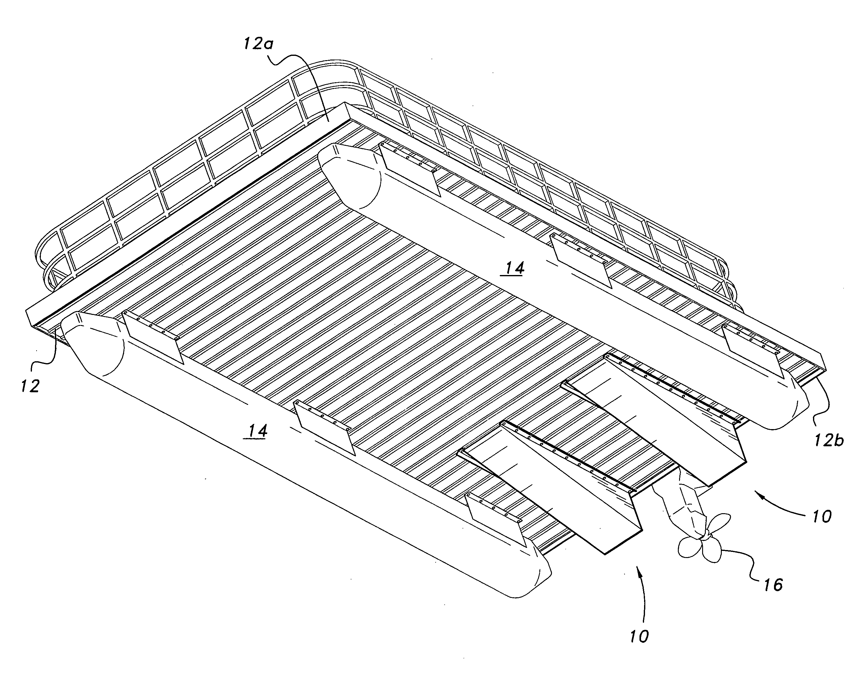
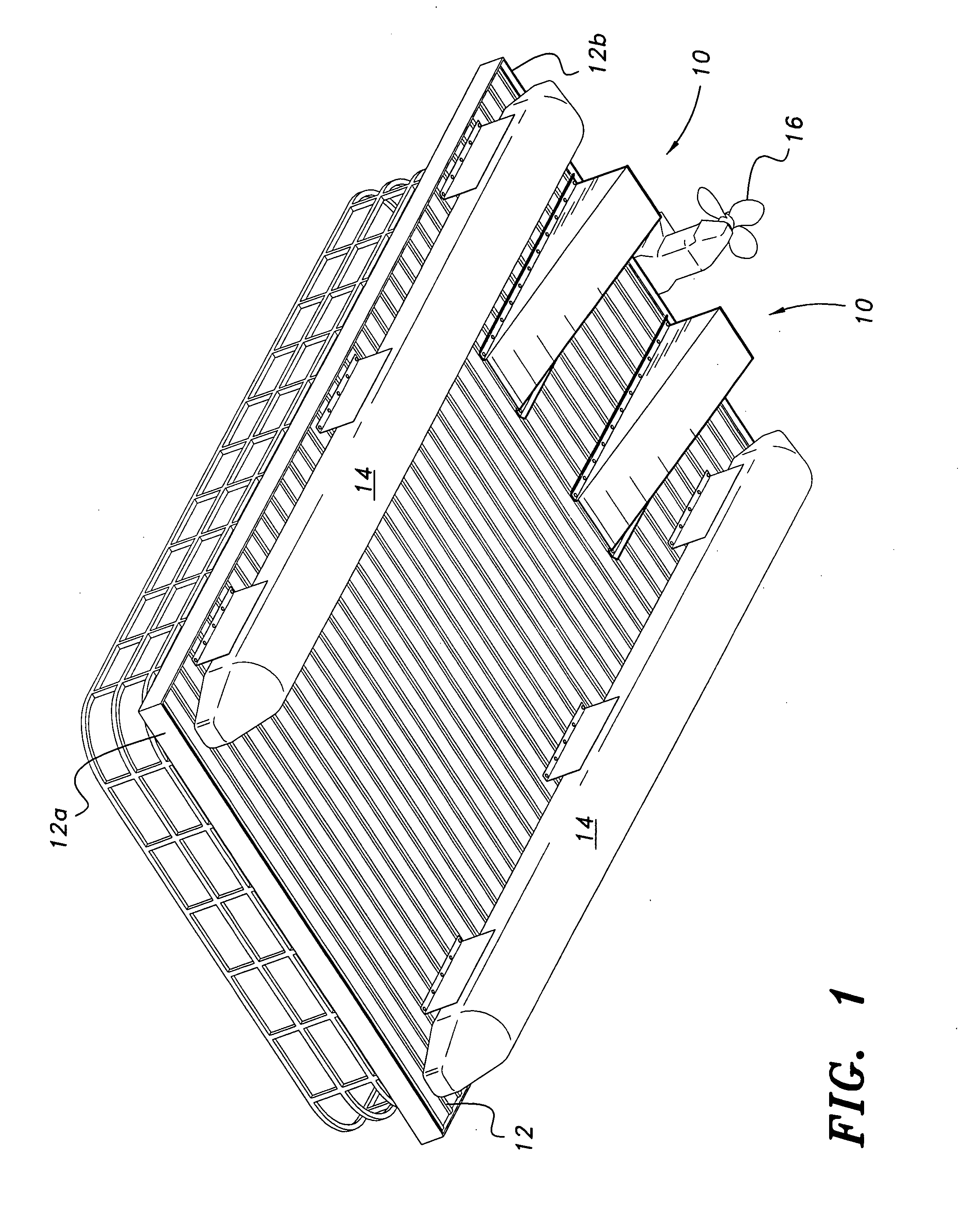
[0014]Referring to FIG. 1, the pontoon planer is a foil generally used as a pair of foils, which are generally indicated at 10 in the drawing. The planer foils 10 are attached to the undersurface of a boat 12, which has a pair of conventional pontoons 14 mounted thereto. The pontoons 14 extend in parallel relationship from adjacent the bow 12a to adjacent the stern 12b of the boat 12. A motor mount 16 is disposed at a center aft position of the boat 12. Identically configured planer foils 10 are respectively disposed on the bottom of the boat 12, each foil 10 being positioned adjacent a corresponding pontoon 14, and also being positioned between the respective pontoon 14 and the motor mount 16. The configuration shown in FIG. 1 is a representative configuration, however, and not meant to be limiting. Pontoon boats of other or different configuration may require the different placement of the foil(s) 10.

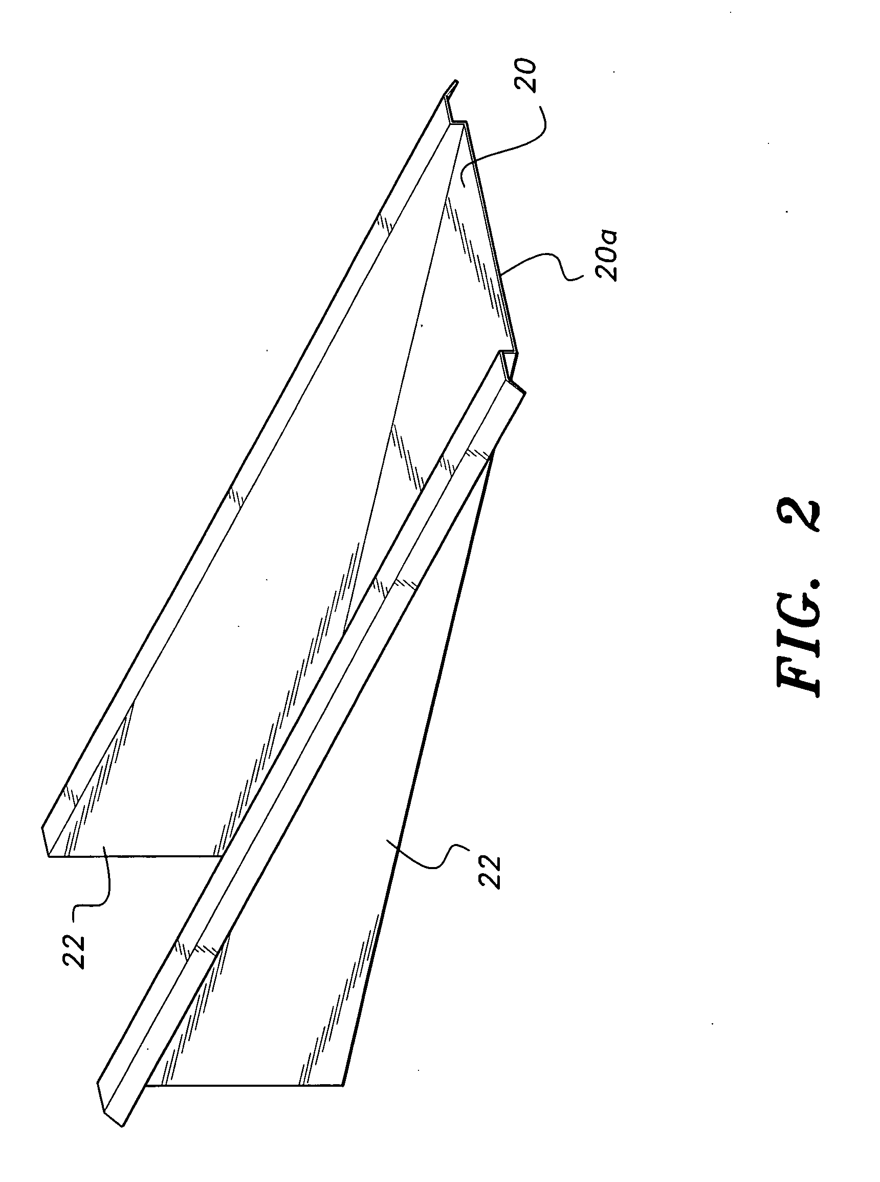
[0015]As best seen in FIGS. 2-5, each of the foils 10 comprises a planar, rectang...


PUM


Abstract

The pontoon planer is a planer assembly for a pontoon boat that includes a pair of planer foils attached to the undersurface of the boat. Each foil presents a wedge-shaped profile, and a respective foil is disposed between the motor mount and a respective pontoon. The planers function to channel water in a downward direction to provide a lifting force to allow the pontoons to plane at lower speeds.

Description

BACKGROUND OF THE INVENTION[0001]1. Field of the Invention[0002]The present invention generally relates to watercraft accessories, and particularly to a pontoon planer assembly for attachment to the bottom of a pontoon boat to allow the boat to plane out in the water at lower RPMs with higher gas mileage and at greater speeds.[0003]2. Description of the Related Art[0004]Pontoon boats conventionally comprise a pair of floatation units (pontoons), spaced in parallel relationship and attached to the undersurface of the boat. The pontoon units are elongate, usually circular and extend from adjacent the bow of the boat toward and adjacent the stern. The pontoons function to provide stability to the boat especially in rough waters. However, pontoons tend to create drag at lower engine RPM, thereby decreasing efficiency (mpg) and maneuverability and increasing operational costs. Heretofore, planer structures have been provided for pontoon boats to alleviate the above conditions. However, n...

Claims


Application Information

Patent Timeline
IPC IPC(8): B63B1/00B63B1/16
CPCB63B1/20B63B1/12
Inventor WILSON, KEITH V.
Owner WILSON KEITH V
Why Eureka
Try Eureka