

Trolley device for conveying laminar elements and conveyor assembly
- Summary
- Abstract
- Description
- Claims
- Application Information
AI Technical Summary
Benefits of technology
Problems solved by technology
Method used
Image

Examples
Embodiment Construction
[0007]The present invention has been developed with the aim of providing a trolley device which is configured as a novelty within the field of application and solves the previously mentioned drawbacks, further contributing other additional advantages which will be obvious from the description below.
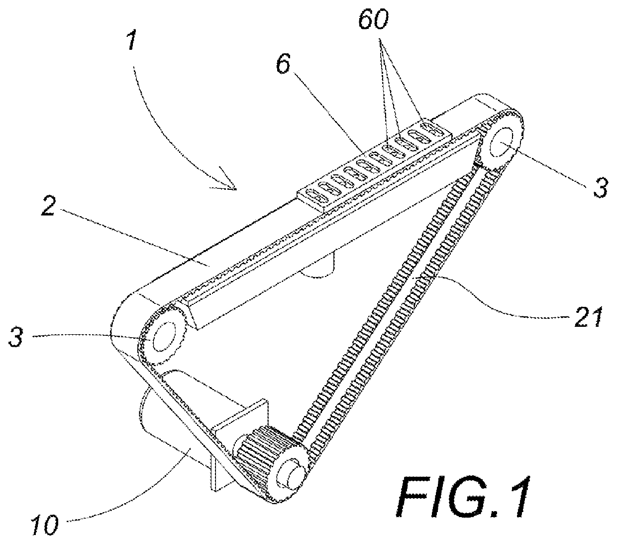
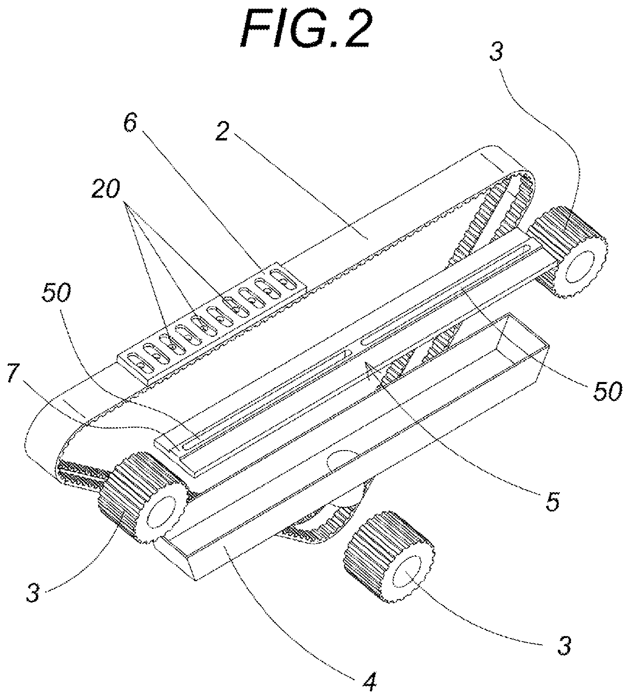
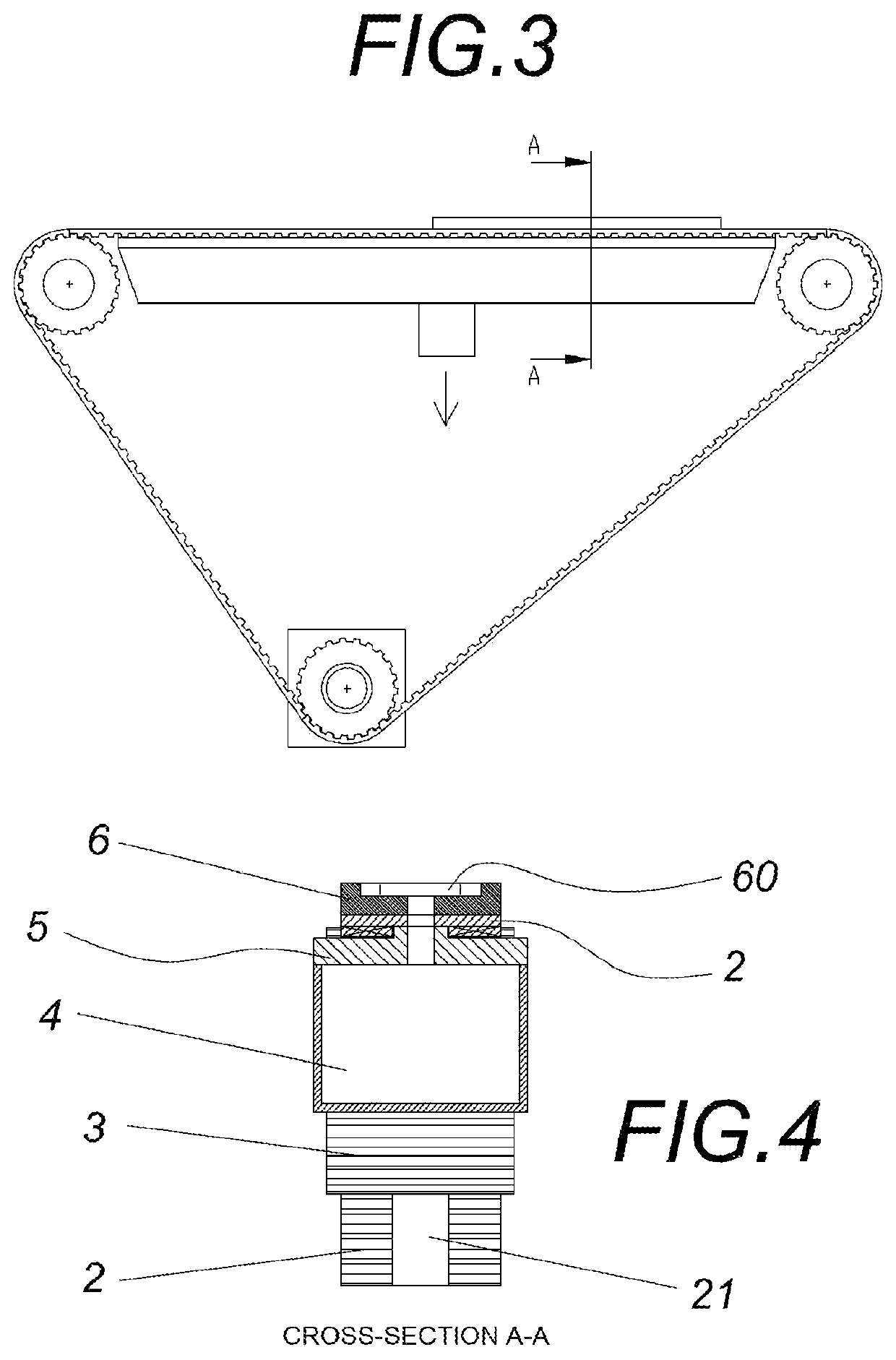
[0008]An object of the present invention is therefore to provide a trolley device for conveying laminar elements, being of the type comprising at least one belt that defines a closed loop, a plurality of pulleys, at least one drive pulley being configured to act on the belt, the pulleys being mounted on a frame with a supporting region over which a section of the belt can be slid and wherein suction means linked to the belt are provided. In particular, the invention is characterized in that the belt comprises at least on the outer face thereof a projecting section of predetermined length that protrudes in height with respect to the rest of the belt, the projecting section being provided w...
PUM
 Abstract
Description
Claims
Application Information