
Heat retaining bottle

a technology of thermos and heat storage bottle, which is applied in the direction of heating apparatus, domestic cooling apparatus, furniture, etc., can solve the problems of not being able to completely prevent heat dissipation, affecting the preservation efficiency, and the sealing degr

Inactive Publication Date: 2011-06-09
LIN CHIEN CHENG
View PDF4 Cites 10 Cited by
  • Summary
  • Abstract
  • Description
  • Claims
  • Application Information

AI Technical Summary

Benefits of technology

[0011]FIG. 2 is an illustration of the first preferred embodiment of this invention. The thermos 20 consists of a body 21, a cap 23 and a heating device. 25, The body 21 has an inner wall 211, an outer wall 213 and a bottle opening 215, where an intermediate space 217 is formed between the inner wall 211 and the outer wall 213. The cap 23 is fitted to the bottle opening 215. The heating device 25 contains an induction coil 251, a donut magnet 253 and a resistance heater 255. The induction coil 251 is wound in the inner wall 211. The donut magnet 253 is placed in the intermediate space 217 and it can move freely within the intermediate space 217. The resistance heater 255 is electrically connected to the induction coil 251 and touches the inner wall 211.
[0013]FIG. 3 illustrates the heating device of this invention. In addition to the induction coil 251, donut magnet 253 and the resistance heater 255, the heating device also contains a thermal switch 252, which senses the temperature of the thermos 20, a rectifier 254 and a charger 256. The thermal switch 252 disconnects the electrical connection between the induction coil 251 and the resistance heater 255 when the temperature is higher than a set value, to avoid the danger of continued heating. The direction changes every time the donut magnet moves back and forth, which results in different directions of current. Therefore, this invention can use a rectifier 254 to rectify the induced current first, and then send the current to the charger 256 for charging. Water can be heated as needed or the energy generated can be used on other electrical appliances.
[0015]The thermos 20 contains a body 21, a cap 23 and a heating device 25. The body 21 consists of an inner wall 211, an outer wall 213, a bottle opening 215 and a heating room 219. The heating room 219 is constructed inside the intermediate space 217 between the inner wall 211 and the outer wall 213. The cap 23 is fitted to the bottle opening 215. The heating device 25 contains an induction coil 251, a bar magnet 257 and a resistance heater 255. The induction coil 251 is wound in the heating room 219 and the bar magnet 257 can move freely within the induction coil 251. The resistance heater 255 is electrically connected to the induction coil 251 and touches the inner wall 211.
[0016]The heating principle of this preferred embodiment is identical to the first preferred embodiment. A thermal switch 252, a rectifier 254 and a charger 256 (as shown in FIG. 3) may also be added to the heating device 25 of this preferred embodiment, in order to increase the efficiency of the thermos 20.
[0019]The heating principle of this preferred embodiment is identical to the first preferred embodiment. A thermal switch 252, a rectifier 254 and a charger 256 (as show in FIG. 3) may also be added to the heating device 25 of this preferred embodiment, in order to increase the efficiency of the thermos 20.

Problems solved by technology

However, a typical container usually cannot keep the water warm.
Its sealing degree also affects the preservation efficiency.
But up to now, there is not a thermos which can completely prevent heat dissipation.
Therefore, the thermos 10 cannot fully satisfy the need of a backpacker.

Method used


Image

  • Heat retaining bottle
  • Heat retaining bottle
  • Heat retaining bottle

Examples


Embodiment Construction

[0006]The purpose of this invention is to provide a thermos with automatic heating function and the ability to keep warm.

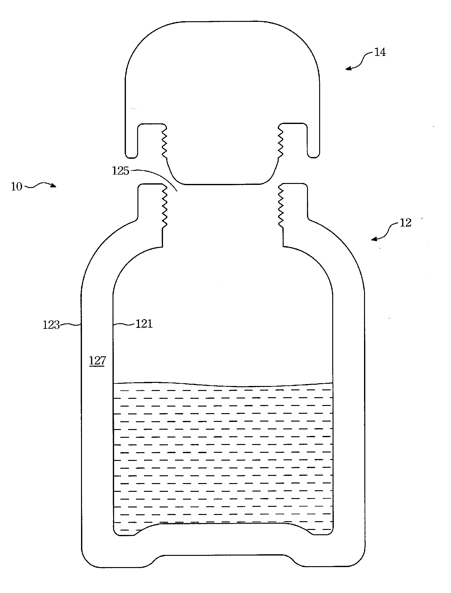
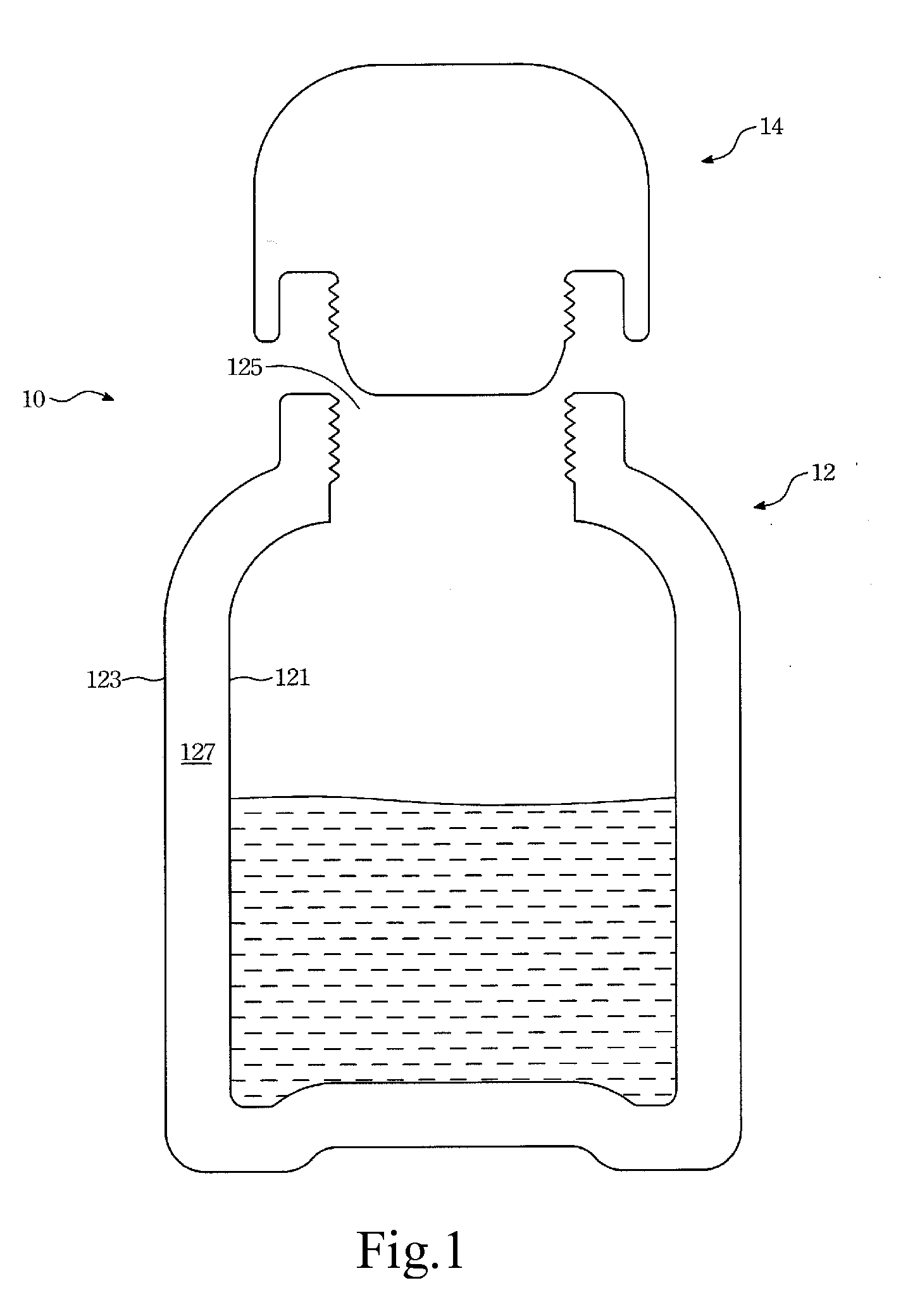
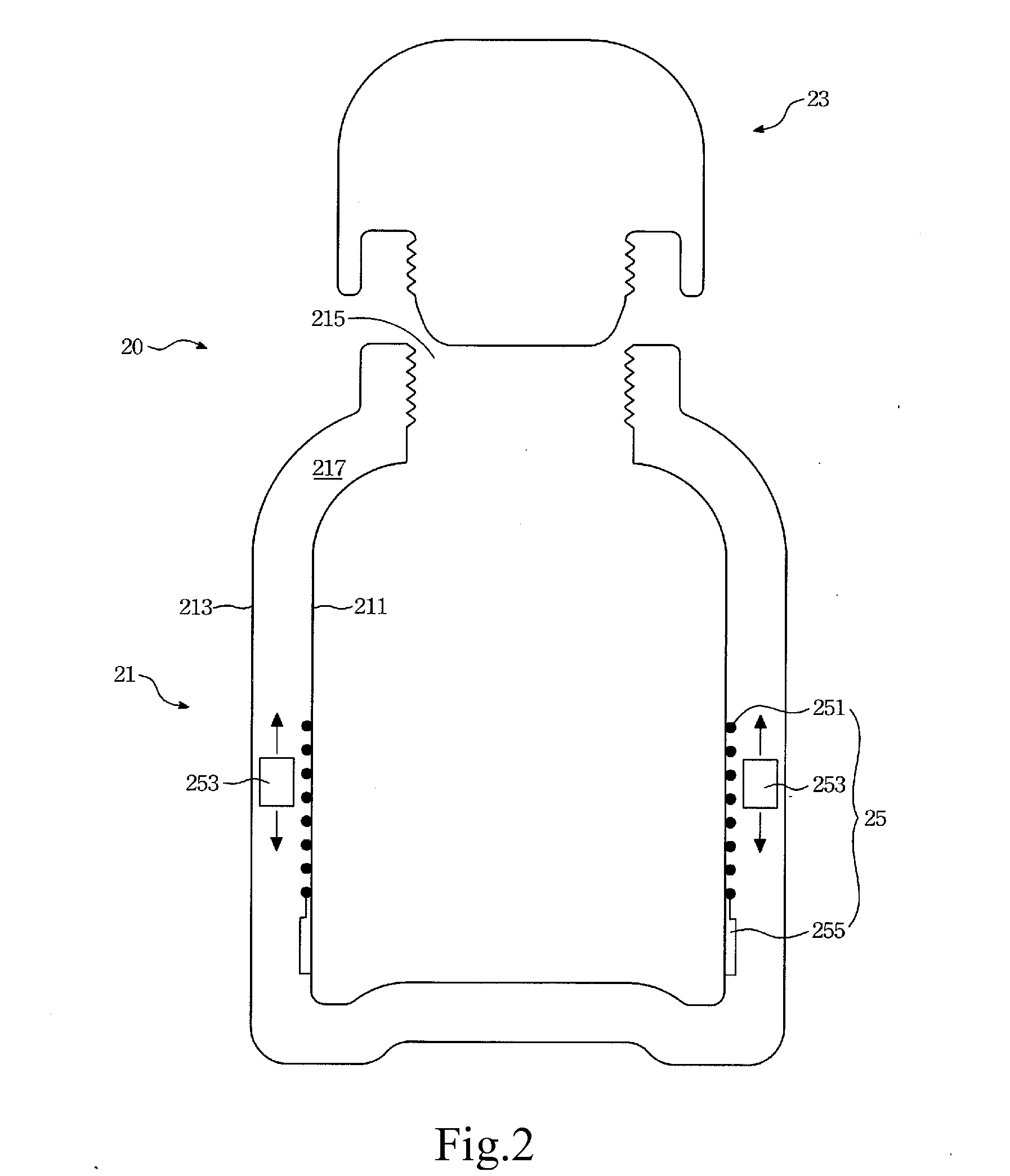
[0007]The thermos of this invention consists of a body, a cap and a heating device. The body has an inner wall, an outer wall and a bottle opening, where an intermediate space is formed between the inner and outer walls. The cap is fitted to the bottle opening. The heating device contains an induction coil, a donut magnet and a resistance heater. The induction coil is wound in the inner wall. The donut magnet is placed in the intermediate space and it can move freely within the intermediate space. The resistance heater is electrically connected to the induction coil and touches the inner wall.

[0008]When the thermos moves, the donut magnet will also move within the intermediate space. At the same time, the induction coil will produce an induced current due to the change of magnetic line of force. When the induced current passes through the resistance heater, it wil...


PUM


Abstract

A thermos consists of a body, a cap and a heating device. The body has an inner wall, an outer wall and a bottle opening, where an intermediate space is formed between the inner and outer walls. The cap is fitted to the bottle opening. The heating device contains an induction coil, a donut magnet and a resistance heater. The induction coil is wound in the inner wall. The donut magnet is placed in the intermediate space and it can move freely within the intermediate space. The resistance heater is electrically connected to the induction coil and touches the inner wall.

Description

FIELD OF THE INVENTION[0001]This invention concerns a thermos with a heating function.DESCRIPTION OF RELATED ART[0002]Water is essential to daily life. In order to be accessible to water at all time, people choose to use containers to hold water. However, a typical container usually cannot keep the water warm. But in many occasions, for example, camping and hiking, hot water is needed for food preparation. Therefore, a thermos is an essential device for backpackers and outer people.[0003]FIG. 1 is an illustration of the prior art. The thermos 10 consists of a body 12 and a cap 14. The body 12 has an inner wall 121, an outer wall 123 and a bottle opening 125.[0004]The inner wall 121 is a hollow container used to hold water. The bottle opening 125, where the water can flow in, is located above the inner wall 121. The outer wall 123 is located outside the inner wall 121. An intermediate space 127 is formed between these two walls. In order to achieve heat preservation, the intermediate...

Claims


Application Information

Patent Timeline
Patent Type & Authority Applications(United States)
IPC IPC(8): A47J36/26A47J41/00B65D81/38
CPCA45F3/18B65D81/3484A47J41/0072A47J41/005
Inventor LIN, CHIENCHENGZHENG, YUEFENG
Owner LIN CHIEN CHENG
Learn More