Absorptive article

a technology of absorptive articles and absorption pads, applied in the field of absorptive articles, can solve the problems of increased cost, labor-intensive manufacturing processes, and increased labor costs, and achieve the effects of avoiding stuffiness, preventing permeation and leakage, and increasing the absorption of articles

Inactive Publication Date: 2011-06-09
UNI CHARM CORP
View PDF9 Cites 2 Cited by
  • Summary
  • Abstract
  • Description
  • Claims
  • Application Information

AI Technical Summary

Benefits of technology

[0015]According to the present invention, the absorptive article can prevent permeation and leakage, because the lower surface of the main absorber and the back sheet on the side-flap portion side are joined. Because the side-flap portions are given as highly-moisture-per

Problems solved by technology

The former of these two last above-described conventional examples is also disadvantageous in that processes in the manufacturing is labor-consuming and consequently raises the cost, because of need of providing the fold-back portions 2130 to the individual side-flap portions

Method used


Image

  • Absorptive article
  • Absorptive article
  • Absorptive article

Examples


embodiment 1-2

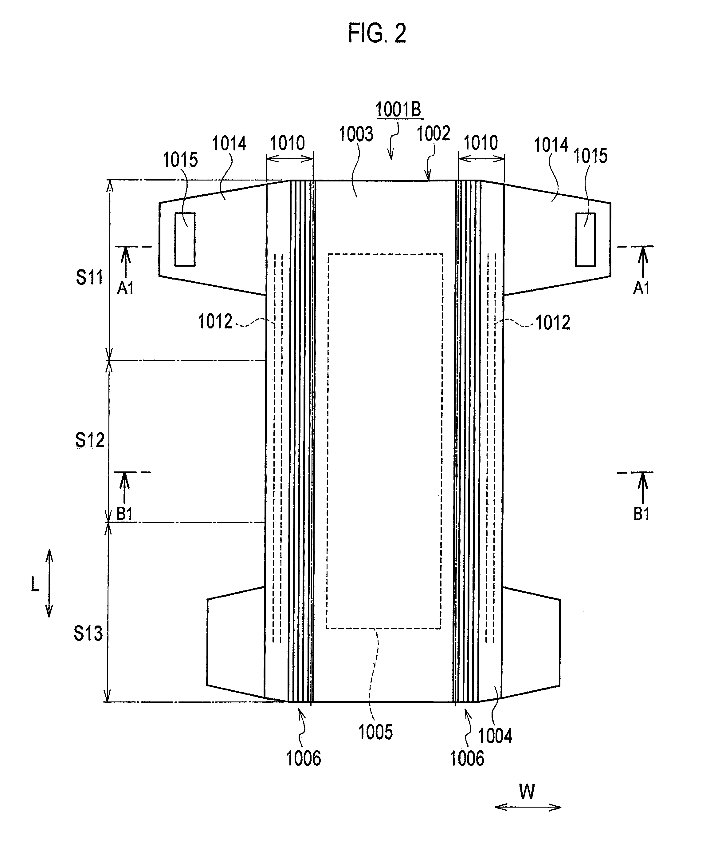
[0049]FIG. 2 to FIG. 7 illustrate an embodiment 1-2 of the present invention. FIG. 2 is an expanded view illustrating a diaper 1001B. FIG. 3 is a sectional view taken along line A1-A1 in FIG. 2. FIG. 4 is a sectional view taken along line B1-B1 in FIG. 2. FIG. 5 and FIG. 6 are plan views of the diaper 1001B illustrating ranges of elevation of moisture permeability. FIG. 7 is a sectional view of a stretching machine.

[0050]In embodiment 1-2 below, an explanation will be made mainly on aspects different from embodiment 1-1, whereas the similar explanation will not be repeated.

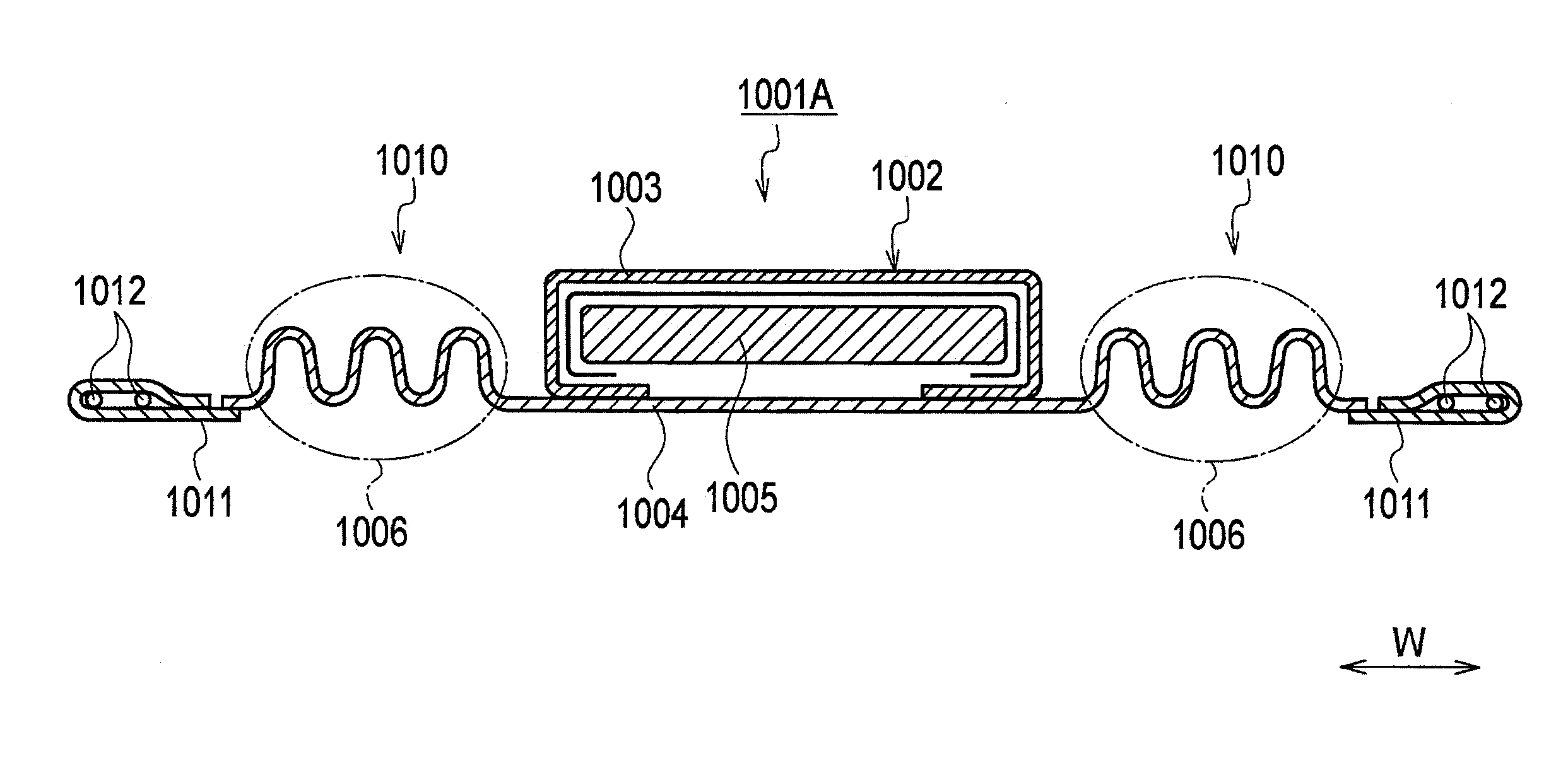
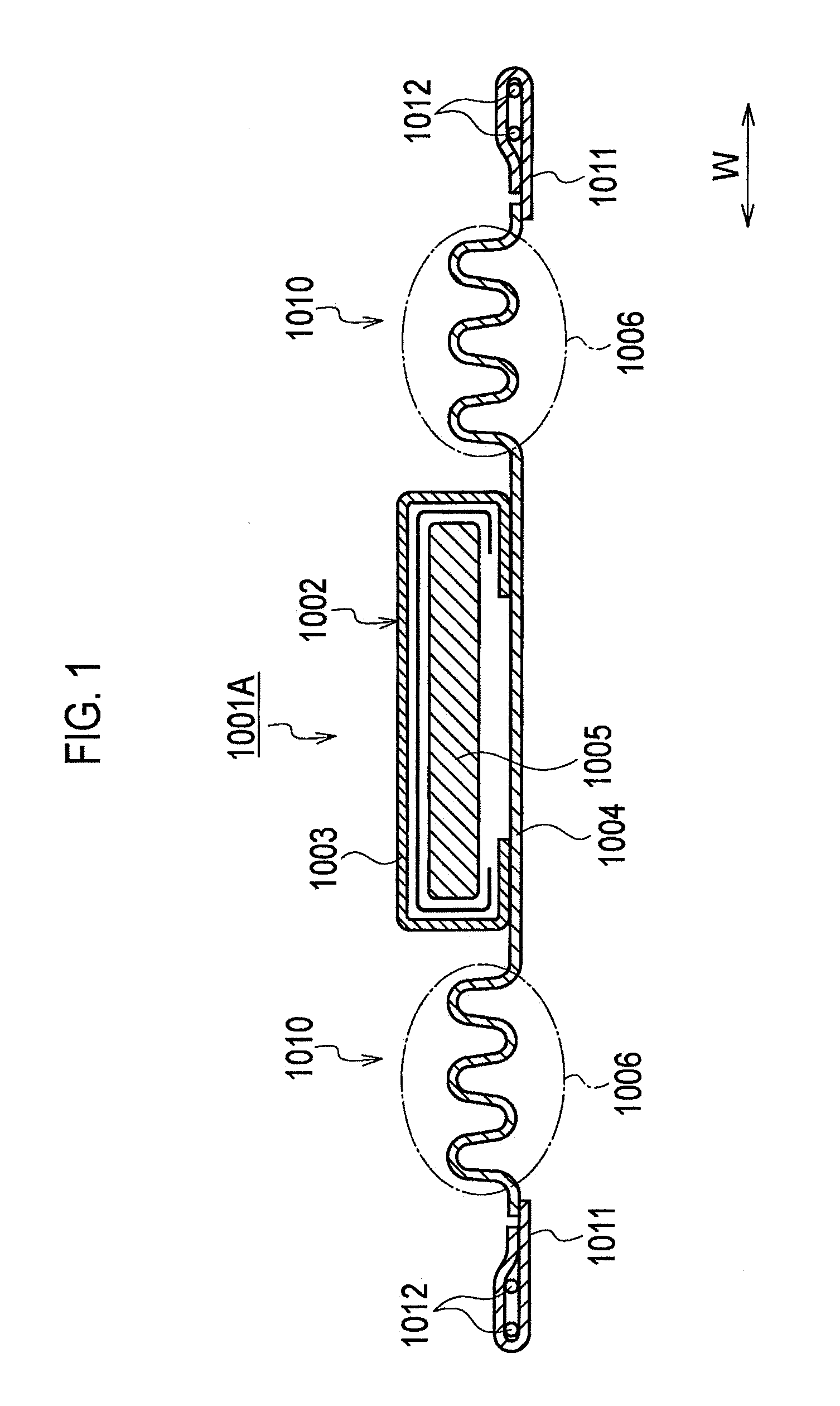
[0051]Similarly to as in embodiment 1-1, the diaper 1001B has the main absorber 1002, and a left-and-right pair of side-flap portions 1010 provided on both sides in the width direction W of the main absorber 1002.

[0052]The main absorber 1002 is composed of at least the liquid-permeable top sheet 1003, the liquid-impermeable back sheet 1004, and absorber 1005 absorbing and retaining fluid. The absorber 1005 is disp...

embodiment 1-3

[0083]FIG. 8 illustrates embodiment 1-3 of the present invention. In a diaper 1001C of this embodiment, the back sheet 1004 is formed by adhering the liquid-impermeable sheet 1013 and the exterior sheet 1011. The top sheet 1003 covers the absorber 1005, and extends sidewards. The top sheet 1003 uses a hydrophilic fluid-permeable sheet. The top sheet 1003, the liquid-impermeable sheet 1013 and the exterior sheet 1011 are adhered. The adhered portions are stretched (elevated in the moisture permeability). In other words, the highly-moisture-permeable regions 1006 are formed in the liquid-impermeable sheet 1013, the exterior sheet 1011, and the top sheet 1003.

[0084]Thus-configured diaper 1001C may guide body fluid once flown from the side portions of the absorber 1005 towards the highly-moisture-permeable regions 1006 of the side-flap portions 1010, back into the absorber 1005, with the aid of the hydrophilic fluid-permeable sheet (top sheet 1003).

embodiment 1-4

[0085]FIG. 9 illustrates embodiment 1-4 of the present invention. In a diaper 1001D of this embodiment, the side-flap portions 1017, 1018 are disposed in two rows on each side, and each of two rows of side-flap portions 1017, 1018 are stretched (elevated in the moisture permeability). Because two rows of side-flap portions 1017, 1018 are disposed on the side portions of the absorber 1005, the diaper 1001D may doubly express its anti-leakage function. Because the liquid-impermeable sheet 1013 composing the back sheet 1004 is covered with the side-flaps 1018, the diaper 1001D may be improved also in the touch.


PUM


Abstract

In an absorptive article the lower surface of the absorptive body and those portions of the rear surface sheet which are located at the side flaps are constructed as a continuous unitized structure. That portion of each side flap which is located between a lateral edge of the side flap and that edge of the side flap which is on the absorptive body side has a high moisture-permeable region having higher moisture permeability than the lower surface of the absorptive body.

Description

TECHNICAL FIELD[0001]The present invention relates to an absorptive article used for sanitary napkin, pantyliner, incontinence pad, absorbent pad and so forth.[0002]The present invention relates also to an absorptive article forming so-called pocket between an absorptive article and the skin of the user, such as diaper.BACKGROUND ART[0003]There has widely been known an absorptive article having a liquid-permeable top sheet, a liquid-impermeable back sheet, and an absorber absorbing and retaining fluid. The absorber is disposed between the liquid-permeable top sheet and the liquid-impermeable back sheet. As for this sort of absorptive article, Patent Document 1 discloses a structure having the top sheet formed by a liquid-impermeable, non-woven fabric, and having a melt-blown layer provided between the absorber and the back sheet.[0004]Patent Document 2 discloses a structure obtained by forming fold-back portions to the liquid-impermeable back sheet, and by bonding the liquid-imperme...

Claims


Application Information

Patent Timeline
IPC IPC(8): A61F13/514A61F13/49
CPCA61F13/49017A61F13/551A61F13/539A61F13/49406
Inventor OKU, TOMOMISAKAGUCHI, SATORU
Owner UNI CHARM CORP
Why Eureka
Try Eureka