A solenoid valve coil assembly

A technology of solenoid valve coils and components, applied in the direction of electromagnets, electrical components, electromagnets with armatures, etc., can solve the problem that the coil and current limiting components cannot be used, the water inlet solenoid valve cannot be used, and the aluminum wire uses too much copper wire. and other problems, to achieve the effect of compact product structure, reduce coil temperature rise, and improve product quality

Active Publication Date: 2022-02-18
HANYU GRP CO LTD
View PDF6 Cites 0 Cited by
  • Summary
  • Abstract
  • Description
  • Claims
  • Application Information

AI Technical Summary

Problems solved by technology

However, this structure cannot meet the design requirements for the electrical connection between the coil and the current-limiting element. According to the content of the parent application specification, the new coil can meet the above design requirements, and can also solve the problem that the existing water inlet solenoid valve cannot use aluminum wires and the use of The technical problem of too many copper wires reduces the cost of the product

Method used


Image

  • A solenoid valve coil assembly
  • A solenoid valve coil assembly
  • A solenoid valve coil assembly

Examples


Embodiment Construction

[0030] The present invention will be described in detail below in conjunction with specific embodiments.

[0031] In this application, all the contents are directly described in the specification of the parent application, or can be inferred without doubt from the specification of the parent application.

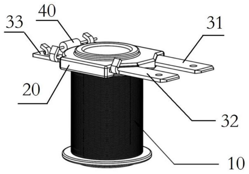
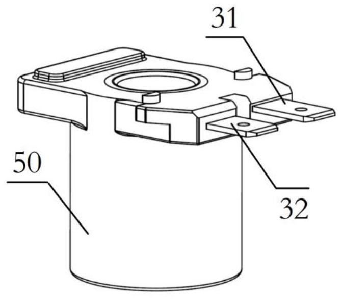
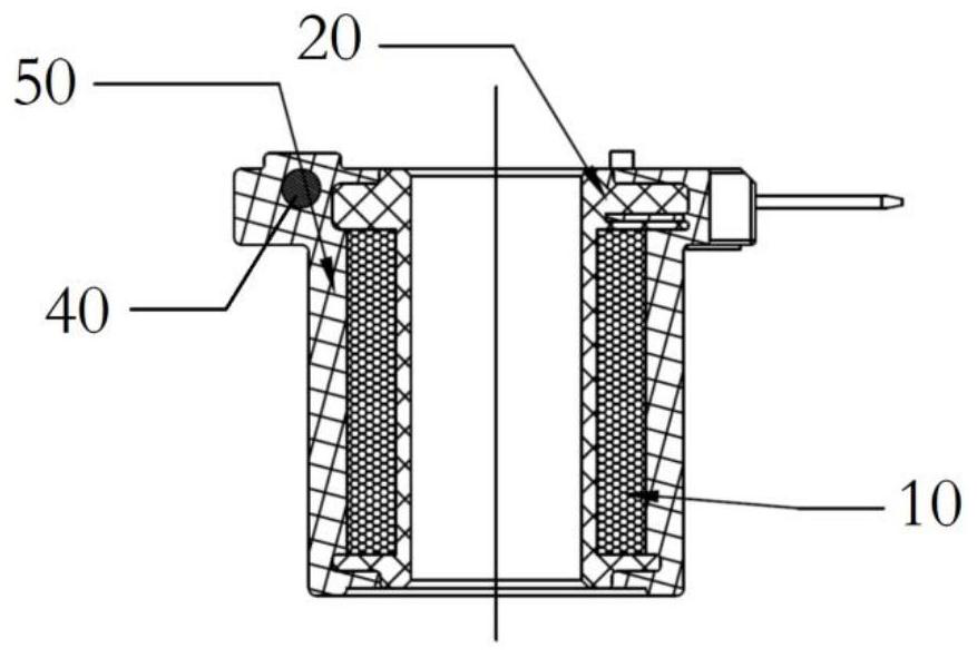
[0032] As the first embodiment of the present invention (embodiment 1 from the specification of the parent application), such as Figure 1-3 As shown, the coil assembly includes a coil 10 , a coil frame 20 , a first insert 31 , a second insert 32 , a third insert 33 and a current limiting element 40 . Such as Figure 4 As shown, the bobbin 20 is a cylindrical plastic part with an end face 21 at one end. The coil 10 is wound on the bobbin cylinder, and the two ends of the coil 10 respectively form the lead-out end and the lead-out end. Such as Figures 1 to 5 As shown, a first insertion piece 31 , a second insertion piece 32 and a third insertion piece 33 are plugged into...


PUM


Abstract

The present invention provides a solenoid valve coil assembly, comprising: a coil frame wound with a coil; one end of which is connected to the first insertion piece of the live wire of the power supply, one end of which is connected to the zero wire of the power supply, and the other end is connected to the The second insertion piece of the coil, and the third insertion piece whose one end is connected to the coil; the current limiting element installed between the other end of the first insertion piece and the other end of the third insertion piece. The invention can effectively meet the design requirements of the electric connection between the coil and the current limiting element, increase the force of the movable iron core driven by the magnetomotive force, simplify the production process of the electromagnetic valve, and reduce the production cost.

Description

technical field [0001] The invention relates to the technical field of water inlet solenoid valve manufacturing, and the IPC classification belongs to F16K31 / 02. Background technique [0002] This application is a divisional application of CN201910485701.1. The structure of the existing solenoid valve coil assembly, such as the specification of Chinese patent CN201149123Y Figure 2 to Figure 11 As shown, grooves are opened on the end face side of the frame, which solves the problem of inserting and forming the connecting terminals into the frame. However, this structure cannot meet the design requirements for the electrical connection between the coil and the current-limiting element. According to the content of the parent application specification, the new coil can meet the above design requirements, and can also solve the problem that the existing water inlet solenoid valve cannot use aluminum wires and the use of The technical problem of too many copper wires reduces the...

Claims


Application Information

Patent Timeline
Patent Type & Authority Patents(China)
IPC IPC(8): F16K31/06H01F7/06H01F7/18H01F7/128H01F7/08
CPCF16K31/0675H01F7/06H01F7/1844H01F7/128H01F7/081H01F2007/062
Inventor 王红标敖林徐飞
Owner HANYU GRP CO LTD
Why Eureka
Try Eureka