Image forming apparatus and image forming method

Inactive Publication Date: 2006-02-02
FUJIFILM CORP
View PDF4 Cites 0 Cited by
  • Summary
  • Abstract
  • Description
  • Claims
  • Application Information

AI Technical Summary

Benefits of technology

[0012] The present invention has been designed in consideration of these circumstances, and a first object thereof is to prevent deposition interference, permeation smearing, color smearing, and the like by creating an electric field that can sufficiently exhibit electro rheological effects when ink with electro rheological effects is used; and a second object thereof is to prevent unsatisfactory ejections resulting from the thickening of the ink near the nozzles.

Problems solved by technology

In such image forming apparatuses, when second ink droplets are deposited so as to overlap first ink droplets that are deposited first on the recording medium, if the first ink droplets remain unsettled on the recording medium, the ink droplets mix together in the areas where the second ink droplets and the unsettled first ink droplets overlap, which blurs the original shape of the dots, creates mixed colors when inks of different colors are used, and causes degradation in the image.
However, it has been made clear though the experiments of the inventors that the viscosity of the liquid deposited on the recording medium does not increase sufficiently even if an electric field is formed by the electric field formation devices disclosed in Japanese Patent Application Publication Nos. 2-212149, 5-4342, and 5-4343, which results in deposition interference between droplets on the recording medium, and in permeation smearing or color smearing in which the deposited droplets permeate and smear on the recording medium.

Method used


Image

  • Image forming apparatus and image forming method
  • Image forming apparatus and image forming method
  • Image forming apparatus and image forming method

Examples


first embodiment

; Overall Configuration of Inkjet Recording Apparatus

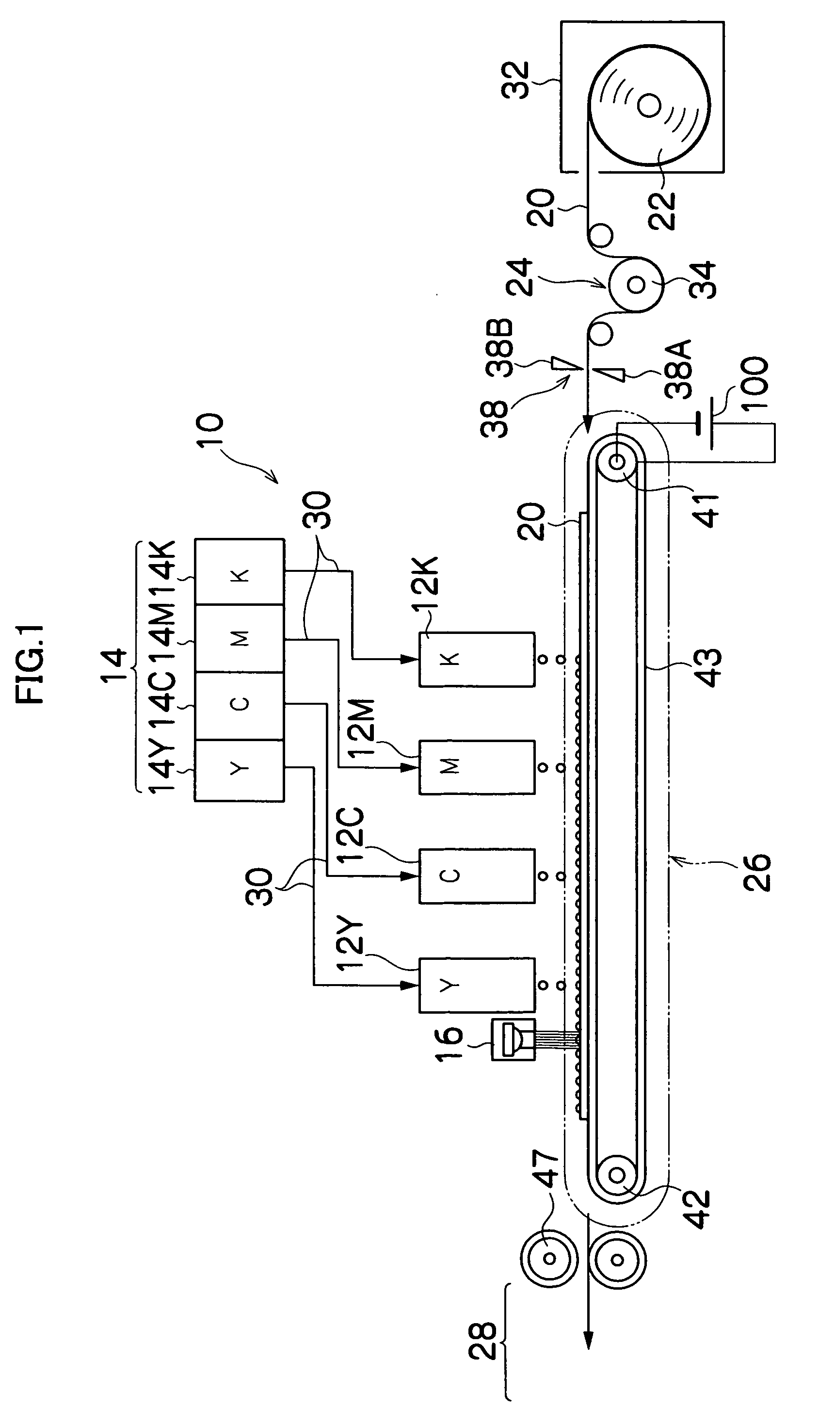
[0061]FIG. 1 is a general schematic drawing of an inkjet recording apparatus 10 according to a first embodiment of the present invention. As shown in FIG. 1, the inkjet recording apparatus 10 comprises a plurality of print heads 12K, 12M, 12C, and 12Y provided for each color of ink; an ink storing and loading unit 14 that stores the ink (in the present embodiment, UV-curing ink that has electro Theological effects) to be supplied to the print heads 12K, 12M, 12C, and 12Y; an ultraviolet source (UV source) 16 disposed on the downstream side in the conveyance direction of the print head 12Y (to the left hand in FIG. 1); a medium supply unit 22 that supplies a medium (recording medium) 20; a decurling process unit 24 that removes the curls in the medium 20; a conveying unit 26 that is disposed facing the nozzle surfaces (ink ejection surfaces) of the print heads 12K, 12M, 12C, and 12Y and also facing the light emission surface of the...

second embodiment

[0167] Next, the second embodiment of the present invention will be described.

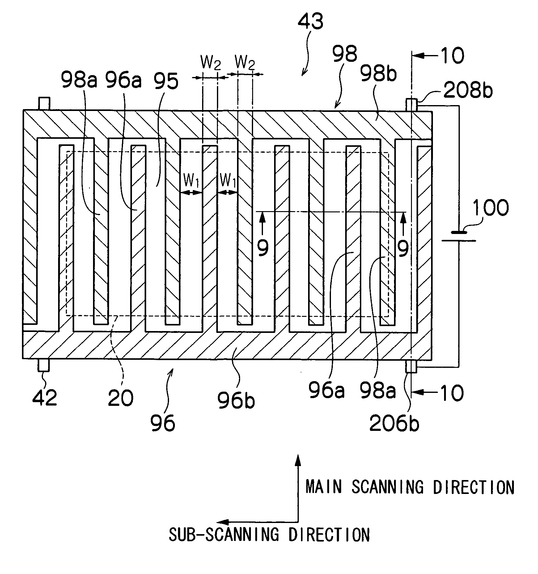
[0168]FIG. 15 is a plan view showing schematic configuration of an electrode layer according to a second embodiment of the present invention. FIG. 16 is a cross-sectional view of the position 16-16 in FIG. 15, for depicting the relationship between the print head 50 and the ink droplets on the medium 20. In FIGS. 15 and 16, identical reference numerals denote parts that are common to FIGS. 11 and 12, and description thereof is omitted here.

[0169] In the electrode layer 92 (see FIG. 9) of the present embodiment, small and substantially square electrode pieces with a positive charge (hereinafter referred to as positive electrode pieces) 96c and electrode pieces with a negative charge (hereinafter referred to as negative electrode pieces) 98c are disposed in the matrix form alternating in the main scanning direction and the sub-scanning direction, as shown in FIG. 15.

[0170] A positive common wire 107 and a...

third embodiment

[0179] Next, the third embodiment of the present invention will be described.

[0180]FIG. 18 is a schematic drawing showing the principal component of the inkjet recording apparatus according to the third embodiment of the present invention. In FIG. 18, identical reference numerals denote parts that are common to FIG. 1, and description thereof is omitted here.

[0181] As shown in FIG. 18, a roller-shaped electrode unit 302 is supported by a support shaft 304, and is configured to be capable of rotating around the support shaft 304 in the direction shown as an arrow in FIG. 18. The print heads 12K, 12M, 12C, and 12Y are disposed in order from upstream to downstream in the rolling direction of the roller-shaped electrode unit 302, and a UV source 16 is provided downstream of the print head 12Y.

[0182] Though not shown in FIG. 18, the roller-shaped electrode unit 302 is composed of a support layer 90, an electrode layer 92, and a low-conductivity layer 94 (see FIG. 9), similar to the be...


PUM


Abstract

The image forming apparatus comprises: an ejection head which ejects droplets having electro rheological effects onto a recording medium; a holding device which holds the recording medium, the holding device being disposed at a position facing an ejection side surface of the ejection head, the recording medium interposing between the ejection head and the holding device; a pair of electrodes which is disposed on the holding device, the pair of electrodes comprising a first electrode and a second electrode; and a voltage application device which applies a voltage to the pair of electrodes.

Description

BACKGROUND OF THE INVENTION [0001] 1. Field of the Invention [0002] The present invention relates to an image forming apparatus and an image forming method, and more particularly to an image forming apparatus and an image forming method that droplets are ejected from nozzles to form images on a recording medium. [0003] 2. Description of the Related Art [0004] Image forming apparatuses with inkjet systems form images on a recording medium by ejecting ink from nozzles provided to a print head. In such image forming apparatuses, when second ink droplets are deposited so as to overlap first ink droplets that are deposited first on the recording medium, if the first ink droplets remain unsettled on the recording medium, the ink droplets mix together in the areas where the second ink droplets and the unsettled first ink droplets overlap, which blurs the original shape of the dots, creates mixed colors when inks of different colors are used, and causes degradation in the image. The mixing ...

Claims


Application Information

Patent Timeline
IPC IPC(8): B41J29/38
CPCB41J2/14008B41J2/065
Inventor YAMANOBE, JUNKADOMATSU, TETSUZOKONNO, MASAAKI
Owner FUJIFILM CORP
Why Eureka
Try Eureka