
Unmanned aircraft and aerial surveillance system for unmanned aircraft

a technology of drones and aircraft, applied in the field of drones, can solve the problems of difficult to ensure the accuracy of the necessary range, and the difficulty of applying millimeter-wave radar to a small unmanned aircra

Active Publication Date: 2011-06-09
MITSUBISHI HEAVY IND LTD
View PDF8 Cites 26 Cited by
  • Summary
  • Abstract
  • Description
  • Claims
  • Application Information

AI Technical Summary

Benefits of technology

[0030]The above object, other objects, the advantageous effects and features of the present invention become clear from the description of the embodiments in conjunction with the following drawings:
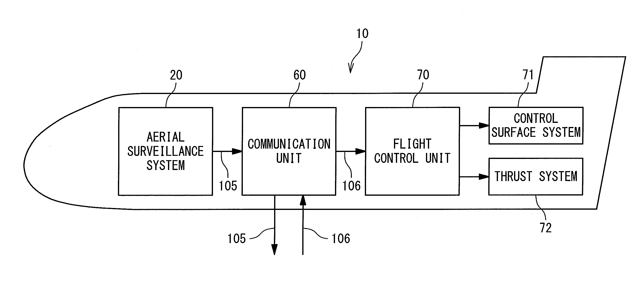
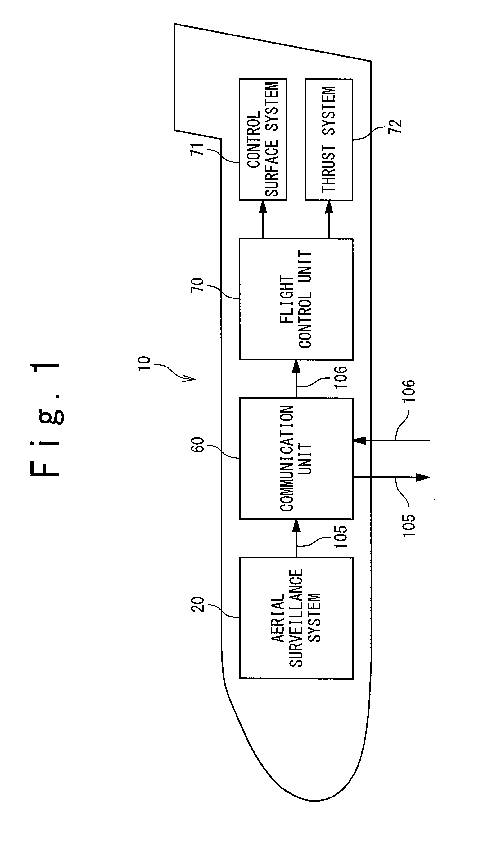
[0031]FIG. 1 is a block diagram showing an unmanned aircraft according to a first embodiment of the present invention;
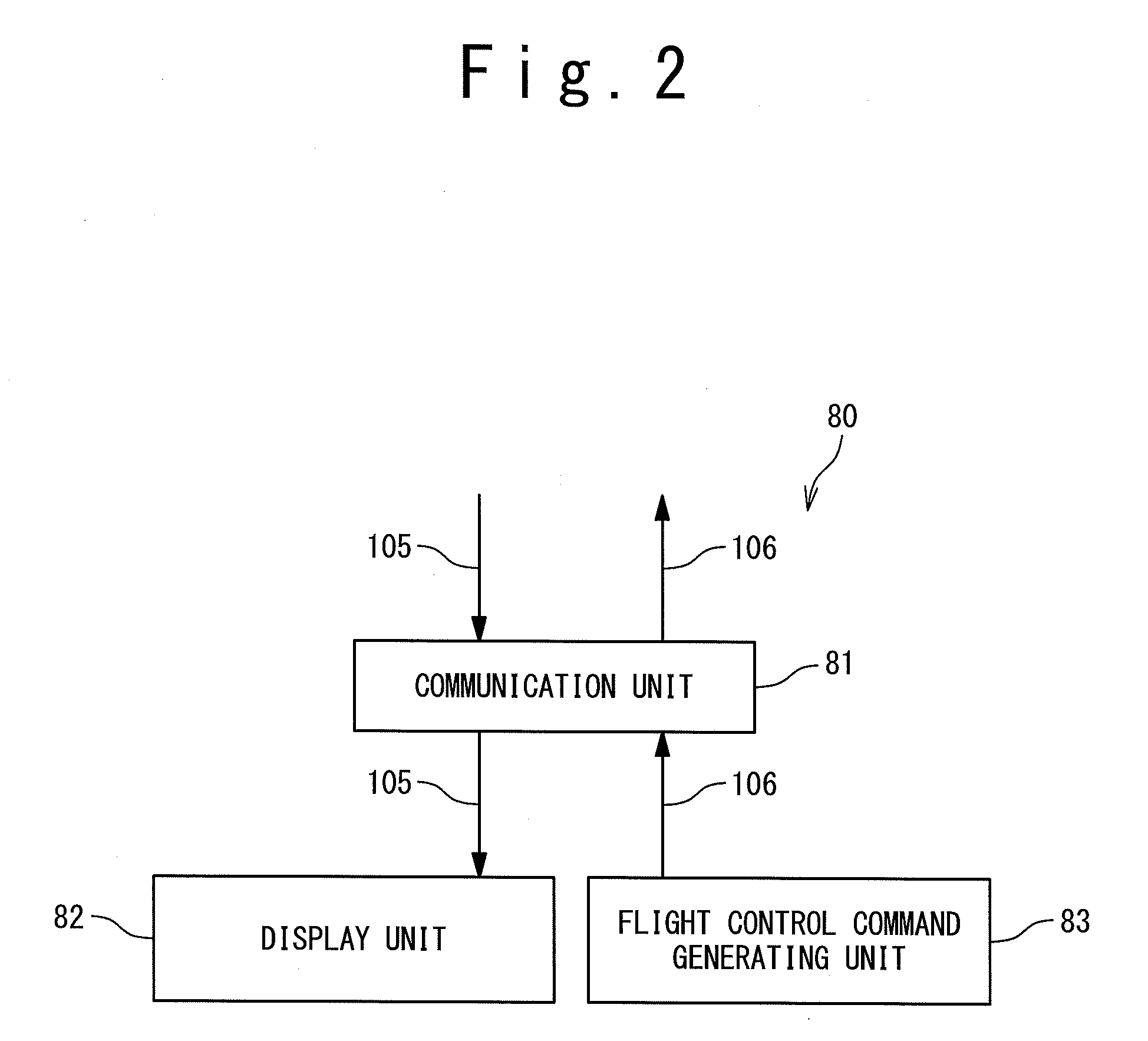
[0032]FIG. 2 is a block diagram showing an external system to the unmanned aircraft in the first embodiment;
[0033]FIG. 3 is an outer appearance of the unmanned aircraft;
[0034]FIG. 4 is a block diagram showing the aerial surveillance system in the first embodiment;
[0036]FIG. 6 is a block diagram showing a rotary optical system according to a second embodiment of the present invention.

Problems solved by technology

However, because the installation of TCAS2 is not obligated to all aircraft, there is a problem of avoidance of midair collision with another aircraft without the installation of TCAS2.
However, it would be difficult to guarantee a necessary range accuracy due to the influence of twist of wings.
However, it would be difficult to apply the millimeter-wave radar to a small unmanned aircraft because the millimeter-wave radar is heavy and large in a consumed power amount.

Method used


Image

  • Unmanned aircraft and aerial surveillance system for unmanned aircraft
  • Unmanned aircraft and aerial surveillance system for unmanned aircraft
  • Unmanned aircraft and aerial surveillance system for unmanned aircraft

Examples


first embodiment

[0038]Referring to FIG. 1, an unmanned aircraft 10 according to the first embodiment of the present invention includes an aerial surveillance system 20, a communication unit 60, a flight control unit 70, a control surface system 71 and a thrust system 72. The aerial surveillance system 20 acquires aerial surveillance data 105 which contains relative position data of flight objects which exist around the unmanned aircraft 10. The communication unit 60 transmits the aerial surveillance data 105 to an external system to the unmanned aircraft to be described later and receives a flight control command 106 from the external system. The flight control unit 70 controls the control surface system 71 or the thrust system 72 based on the flight control command 106.

[0039]Referring to FIG. 2, an external system 80 is provided with a communication unit 81, a display unit 82 and a flight control command generating unit 83. The flight control command generating unit 83 is provided with an input se...

second embodiment

[0054]Referring to FIG. 6, the unmanned aircraft, the aerial surveillance system for the unmanned aircraft and the aerial surveillance method of the unmanned aircraft according to a second embodiment of the present invention will be described. The unmanned aircraft, the aerial surveillance system for the unmanned aircraft and the aerial surveillance method of the unmanned aircraft according to the present embodiment are the same as those of according to the first embodiment except that the rotary optical system 30A is replaced by a rotary optical system 30B.

[0055]Like the rotary optical system 30A, the rotary optical system 30B is provided with an outer cylinder 31, the beam splitter 33, the camera 34 and the laser ranging system 37. However, the rotary optical system 30B is not provided with the reflector 32. The camera 34 images the image in the field of view 93 through the beam splitter 33. The light from a point in the field of view 93 transmits through the beam splitter 33 and ...


PUM


Abstract

An unmanned aircraft includes a camera, a laser ranging system and a driving unit. The laser ranging system measures a distance to an object in the field of view of the camera. The driving unit rotates the field of view. Thus, it is possible to acquire relative position data of the object around the unmanned aircraft with a small and light-weight unit.

Description

TECHNICAL FIELD[0001]The present invention is related to an unmanned aircraft, especially to an aerial surveillance of the unmanned aircraft.BACKGROUND ART TCAS2 (Traffic alert and Collision Avoidance System 2) is known as a system for avoiding midair collision of aircrafts. The aircraft installed with TCAS2 inquires to other aircrafts around the own aircraft and responds to the inquiry from the other aircraft. Based on the inquiry and response, TCAS2 judges whether or not other aircrafts having a risk of the midair collision exist around the own aircraft, and warns a pilot of the existence of the other aircrafts having the risk of the midair collision. The installation of TCAS2 is obligated in a turbine aircraft on which 19 or more passengers board.[0002]However, because the installation of TCAS2 is not obligated to all aircraft, there is a problem of avoidance of midair collision with another aircraft without the installation of TCAS2. In a manned aircraft that a pilot is on board...

Claims


Application Information

Patent Timeline
IPC IPC(8): G06F17/00H04N7/18G01C3/08G01S17/86
CPCB64C39/024B64C2201/127G01S7/4817H04N7/183G03B13/20G03B37/04G01S17/023G01S17/86B64U10/25B64U2101/31B64U20/80B64D47/08B64U2101/30
Inventor SUZUKI, SATOSHI
Owner MITSUBISHI HEAVY IND LTD
Learn More