Clamp device for telescopic poles

Inactive Publication Date: 2011-06-16
UNION METAL CORP
View PDF8 Cites 10 Cited by
  • Summary
  • Abstract
  • Description
  • Claims
  • Application Information

AI Technical Summary

Benefits of technology

[0006]In one aspect of the disclosure, a clamp may be designed and built for a particular application. The clamp may be affixed to, or attached at a specific joint on an existing telescopic pole structure. The clamp may include two or more portions that may comprise steel shells. The shells may be shaped to match the outside diameter(s) of an existing telescopic joint. These shaped shells may

Problems solved by technology

There have been many failures of telescopic pole joints due to fatigue loading caused by fluctuating winds.
In many instances, t

Method used


Image

  • Clamp device for telescopic poles
  • Clamp device for telescopic poles
  • Clamp device for telescopic poles

Examples


example

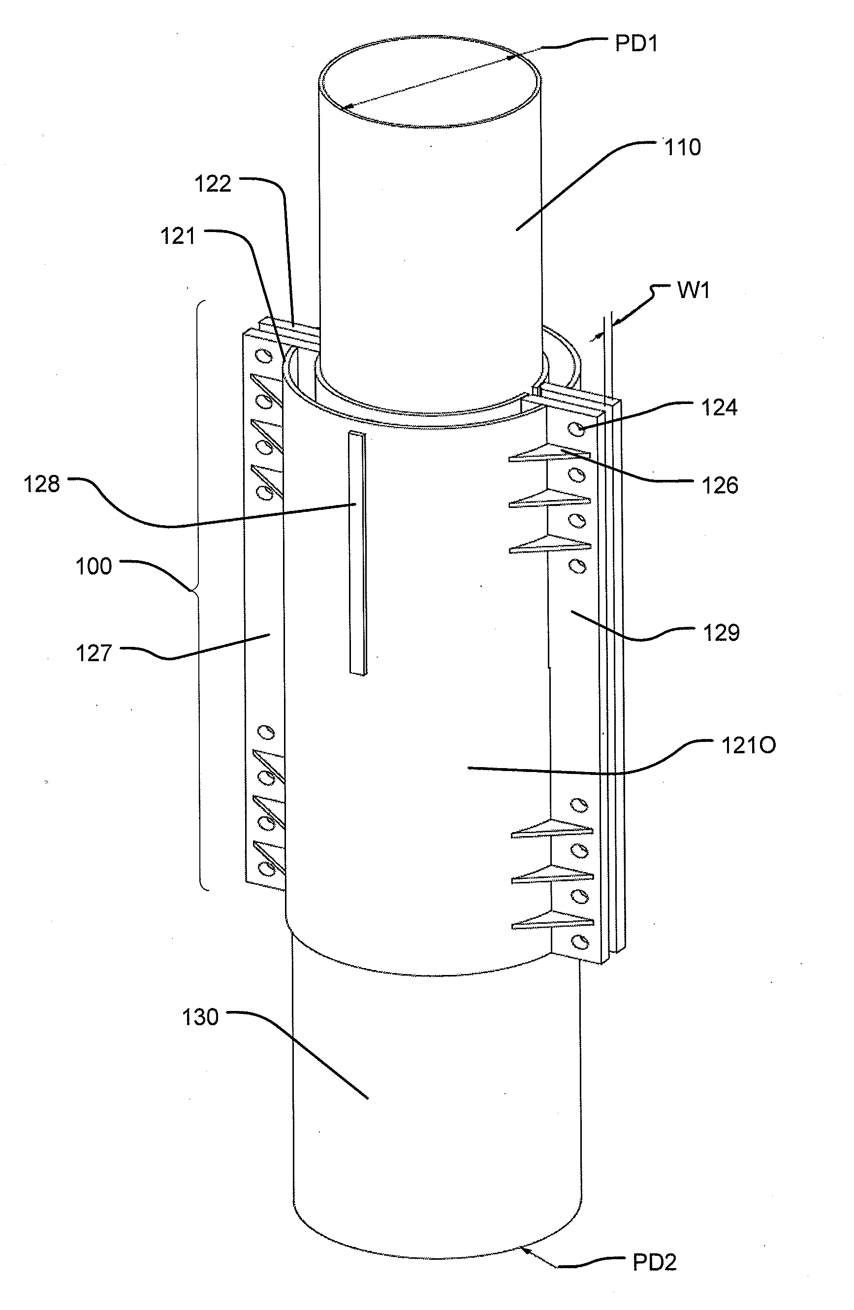
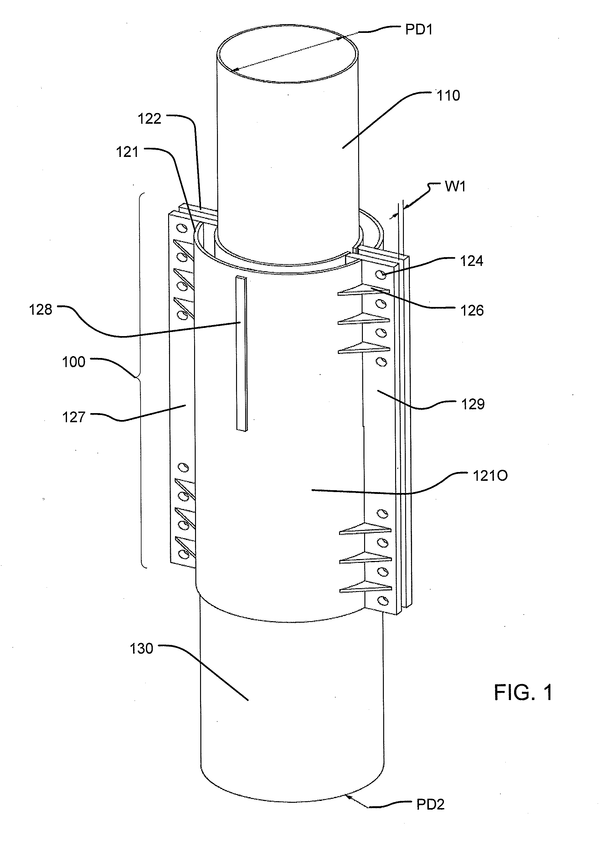
[0037]According to one, non-limiting example of the disclosure, the clamp 100 and the telescopic tower pole portions 110, 130 may be constructed from a material such as, for example, steel, which may have the following non-limiting examples of grades, thicknesses and dimensions (Tables 1-4).

TABLE 1Upper Tower Pole Portion 110Outer diameter PD124in. (inches)Wall thickness0.375in.Material yield35ksi. (kilopound-per-in.2)Section modulus161.8586in.3Moment of inertia1942.283in.4Allow bending moment3738.934k-in. (kilopound-per-in.)

TABLE 2Lower Telescopic tower pole portion 130Outer diameter PD230in.Wall thickness0.5inMaterial yield35ksiSection modulus336.1479in.3Moment of inertia5042.168in.4Allow bending moment7765.017k-in.

TABLE 3Upper Clamp Portion 121UInner diameter of shell 121O30in.Inner diameter of shell 121I24in.Wall thickness of shell 121O0.375in.Wall thickness of shell 121I0.375in.Material yield36ksi.Section modulus407.2074in.3Moment of inertia shell 121O4127.649in.4Moment of iner...


PUM


Abstract

A clamp is designed and built for a particular application. The clamp may be affixed to, or attached at a specific joint on an existing telescopic pole structure. The clamp may be made in two or more sections that comprise shells that have been shaped to match the outside diameters of both sections of the existing telescopic joint.

Description

CROSS REFERENCE TO PRIOR APPLICATIONS[0001]This application claims priority to and the benefit thereof, under 35 U.S.C. §119(e), from a U.S. Provisional Patent Application, No. 61 / 286,943, filed on Dec. 16, 2009, which is hereby incorporated herein by reference for all purposes as if fully set forth herein.BACKGROUND OF THE DISCLOSURE[0002]1. Field of the Disclosure[0003]This disclosure is directed to a novel method and a novel device for preventing fatigue damage to telescopic poles.[0004]2. Related Art[0005]Telescopic pole joints are frequently used to secure telescopic poles, which are used to support, among other things, billboards, signs, and the like. There have been many failures of telescopic pole joints due to fatigue loading caused by fluctuating winds. In many instances, the industry can not remove the existing poles without losing the rights to erect new ones of similar size at the same location.SUMMARY OF THE DISCLOSURE[0006]In one aspect of the disclosure, a clamp may ...

Claims


Application Information

Patent Timeline
IPC IPC(8): F16B2/06
CPCY10T24/44017F16B7/1418
Inventor WILD, JAMES E.
Owner UNION METAL CORP
Why Eureka
Try Eureka