
Method For The Removal And Condensation Of Vapors

a technology of vaporization and removal, applied in the direction of drying machines, drying, lighting and heating apparatus, etc., can solve the problems of collection and recovery of vaporized hydrocarbons

Active Publication Date: 2011-06-16
RED LEAF RESOURCES
View PDF100 Cites 29 Cited by
  • Summary
  • Abstract
  • Description
  • Claims
  • Application Information

AI Technical Summary

Benefits of technology

"The invention is a method for removing, condensing, and recovering vapors from a heated enclosed space. The method involves using an insulative particulate layer made of earthen material with a temperature gradient, which allows the vapors to pass through and be cooled as they move from the inside to the outside of the enclosed space. The vapors that do not liquefy are then collected. The invention can be used in various applications such as industrial processes or waste treatment."

Problems solved by technology

One problem encountered in processing such hydrocabronaceous materials is the collection and recovery of vaporized hydrocarbons from within the enclosed or encapsulated volume.

Method used


Image

  • Method For The Removal And Condensation Of Vapors
  • Method For The Removal And Condensation Of Vapors

Examples


Embodiment Construction

[0011]Reference will now be made to exemplary embodiments and specific language will be used herein to describe the same. It will nevertheless be understood that no limitation of the scope of the invention is thereby intended. Alterations and further modifications of the inventive features described herein, and additional applications of the principles of the invention as described herein, which would occur to one skilled in the relevant art and having possession of this disclosure, are to be considered within the scope of the invention. Further, before particular embodiments of the present invention are disclosed and described, it is to be understood that this invention is not limited to the particular process and materials disclosed herein as such may vary to some degree. It is also to be understood that the terminology used herein is used for the purpose of describing particular embodiments only and is not intended to be limiting, as the scope of the present invention will be def...


PUM


Abstract

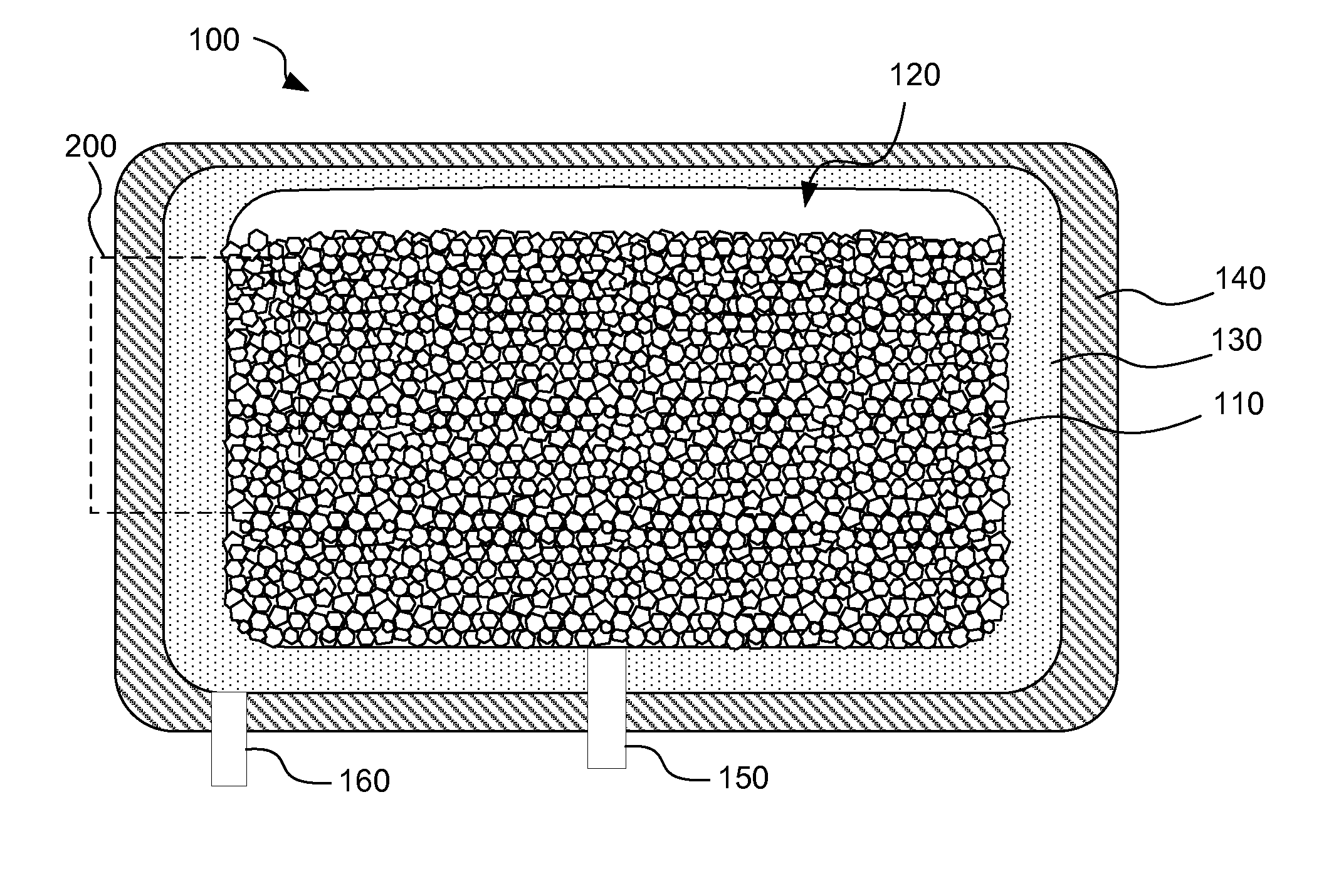
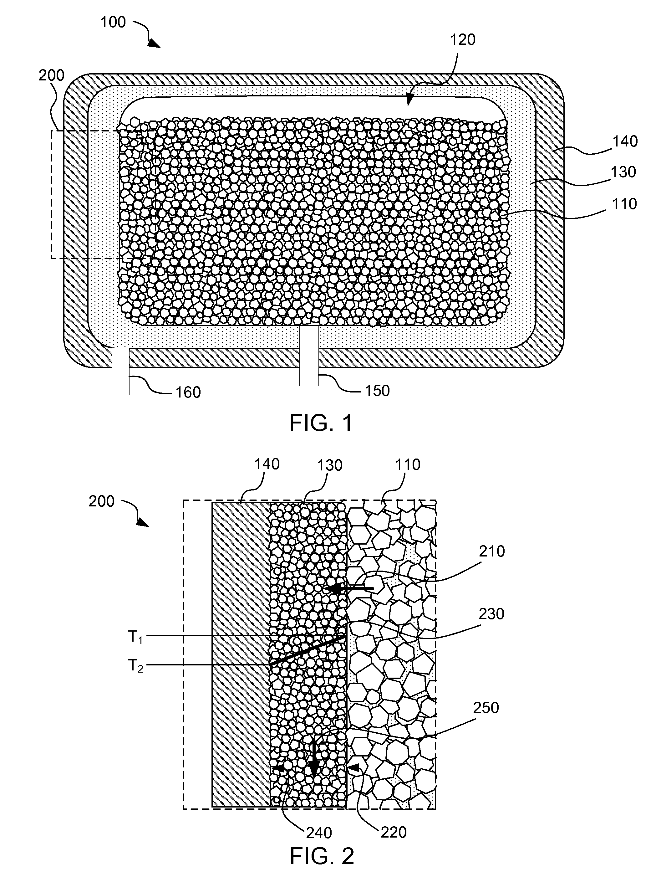
A method for removal and condensation of vapors from within an enclosed space (120) is disclosed. An enclosed space (120) containing material (110) is surrounded by an insulative permeable layer (130) having a lowering temperature gradient (230) between the inner surface (220) and the outer surfaces (240). The insulative layer (130) may also be covered by an impermeable layer (140). Heating the material (110) in the enclosed space (120) causes the formation of vapors at a positive pressure within the enclosed space (120). Vapors pass through the inner surface (220) of the insulative permeable layer (130) and contact the permeable materials and are condensed by the lowering temperature within the insulative layer (130). The condensate liquid passes downwardly through the insulative layer (130) for collection. The positive pressure within the heated enclosed space (120) and the condensation and lowering of pressure and temperature within the insulative layer (130) serves to draw additional vapors from within the enclosed space (120) into the insulative layer (130) for condensation and collection.

Description

RELATED APPLICATION[0001]This application claims priority to U.S. Provisional Application No. 61 / 286,900, filed Dec. 16, 2009 entitled “Method for the Removal and Condensation of Vapors,” which is incorporated herein by reference.BACKGROUND OF THE INVENTION[0002]Global and domestic demand for fossil fuels continues to rise despite price increases and other economic and geopolitical concerns. As such demand continues to rise, research and investigation into finding additional economically viable sources of fossil fuels correspondingly increases. Historically, many have recognized the vast quantities of energy stored in oil shale, coal and tar sand deposits.[0003]One method and system for the recovery of hydrocarbons from such materials is disclosed and claimed in U.S. application Ser. No. 12 / 028,569, filed Feb. 8, 2008 which is incorporated herein in its entirety by reference. In that application, a method of recovering hydrocarbons from hydrocarbonaceous materials is disclosed inclu...

Claims


Application Information

Patent Timeline
Patent Type & Authority Applications(United States)
IPC IPC(8): F26B23/00
CPCC10G1/002C10G2300/1011C10G31/06C10G1/008Y02P30/20F26B25/005
Inventor PATTEN, JAMES W.
Owner RED LEAF RESOURCES
Learn More