Wrench for use with a drilling apparatus

a technology for drilling apparatus and wrenches, which is applied in the direction of wrenches, spanners, drilling accessories, etc., can solve the problems that the wrenches as originally envisaged and as covered in the above patent cannot be used in association with all drilling apparatus, and achieve the effect of strengthening the gripping engagemen

Active Publication Date: 2011-06-16
GOUWS PETRUS CHRISTIAAN
View PDF5 Cites 12 Cited by
  • Summary
  • Abstract
  • Description
  • Claims
  • Application Information

AI Technical Summary

Benefits of technology

[0012]The displacement mechanism for displacing the carrier member about an axis defined by a drill bit segment positioned within the mouth of the gripping member may be a third hydraulically operable piston / cylinder mechanism, particularly connected for operation between the carrier member and the gripping member, the point of attachment to the gripping member coinciding with the point of attachment of the second piston / cylinder mechanism with the gripping member. The capacity of the third piston / cylinder mechanism particularly is such that a sufficient rotational force can be applied to a drill bit segment gripped within the open mouth formation defined by the gripping member for loosening thereof, the relationship between the second and third piston / cylinder mechanisms being such that where the hydraulic pressure applied by the third piston / cylinder mechanism for loosening a drill bit segment is to exceed the pressure applied by the second piston / cylinder mechanism, the increased pressure is effectively imparted also on the second piston / cylinder mechanism, particularly due to the wedging action on the drill bit segment that enhances the gripping engagement of the drill bit segment by the gripping elements of the gripping member.

Problems solved by technology

It has become apparent that the drill bit wrench forming the subject matter of the Applicant's abovementioned patent is very effective in relation to the required loosening of adjacent drill bit segments, but insofar as the general configuration of different drilling apparatus requires a wrench to operate within different space parameters, the wrench as originally envisaged and as covered in the above patent cannot be employed in association with all drilling apparatus.

Method used


Image

  • Wrench for use with a drilling apparatus
  • Wrench for use with a drilling apparatus
  • Wrench for use with a drilling apparatus

Examples


first embodiment

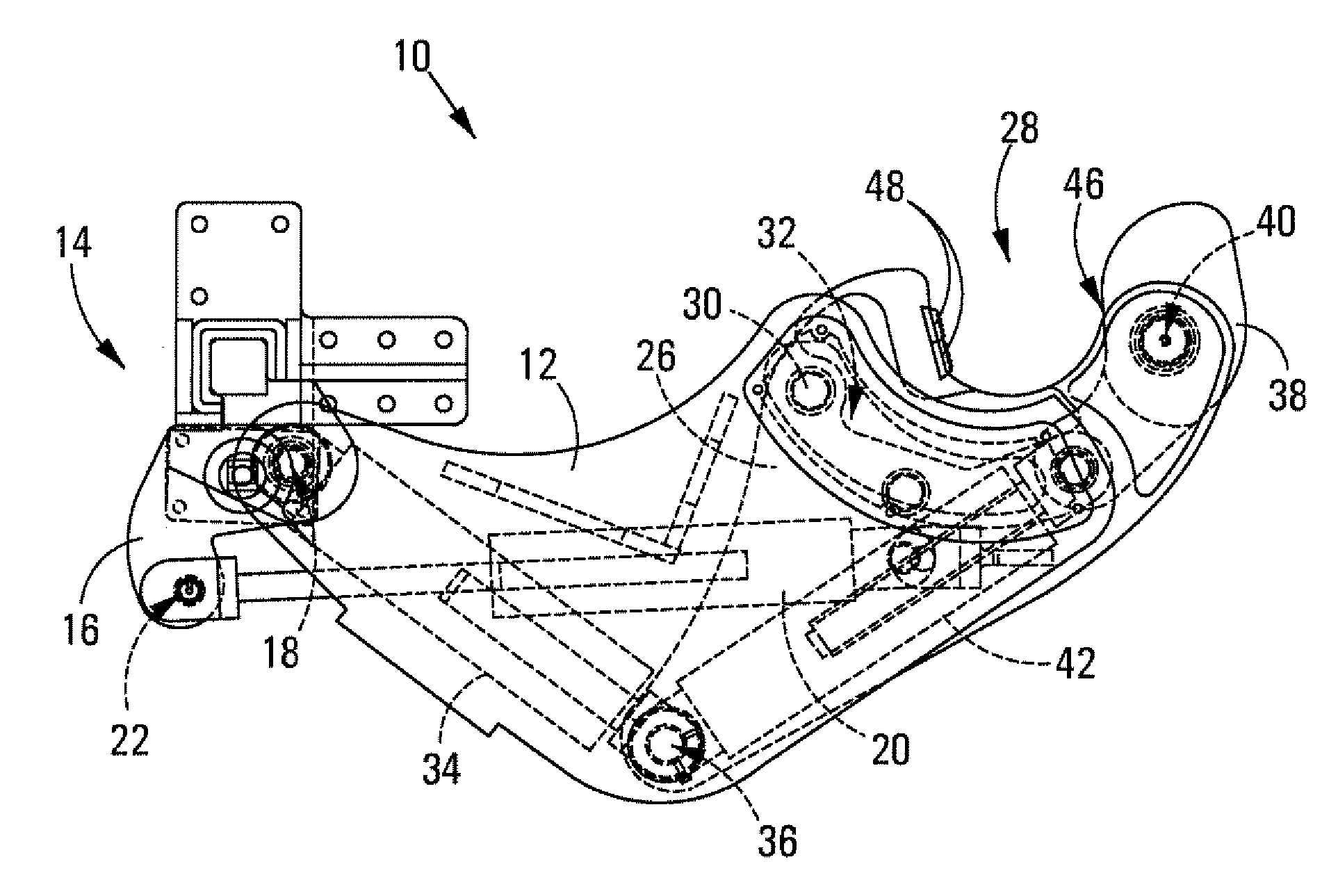
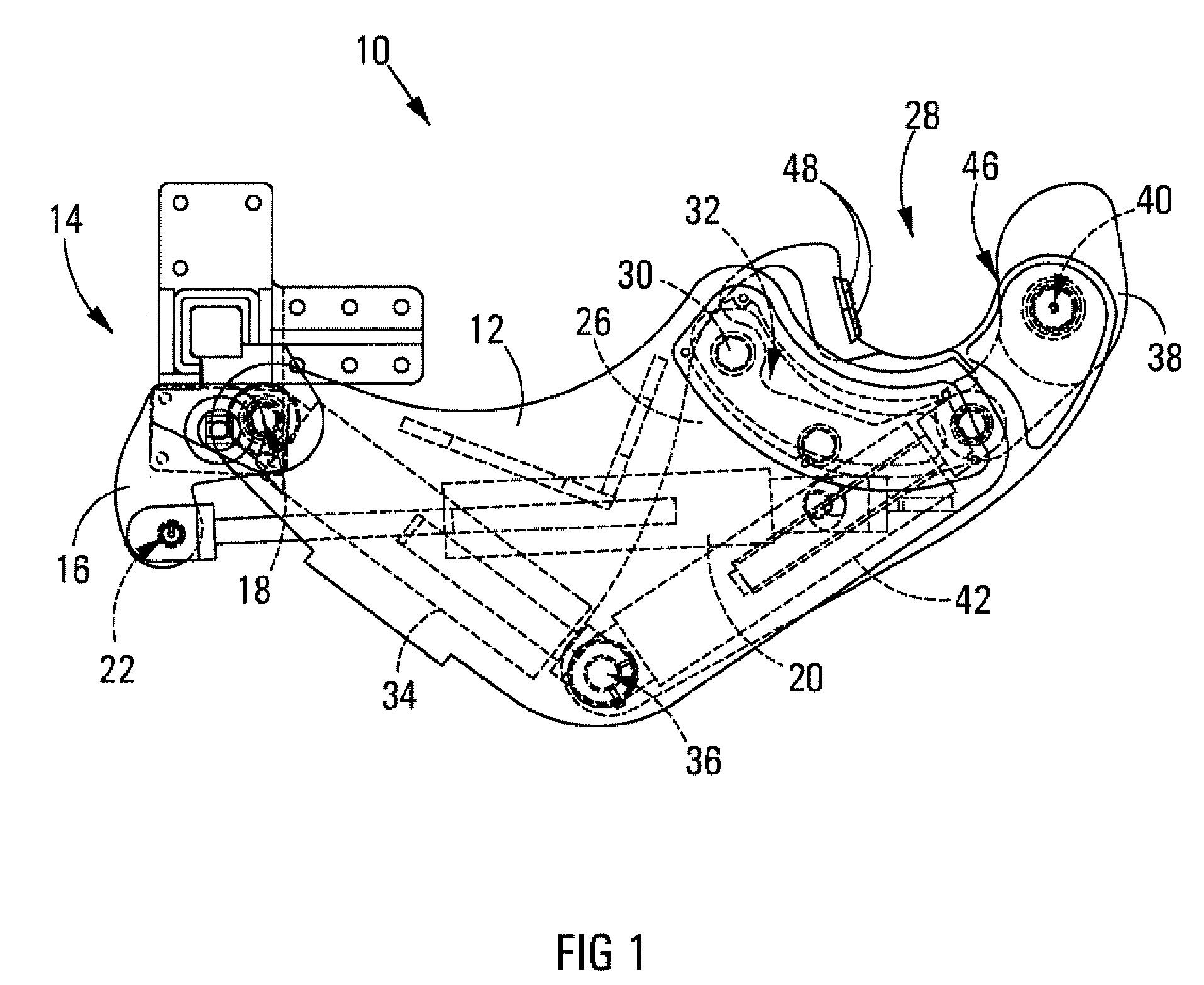
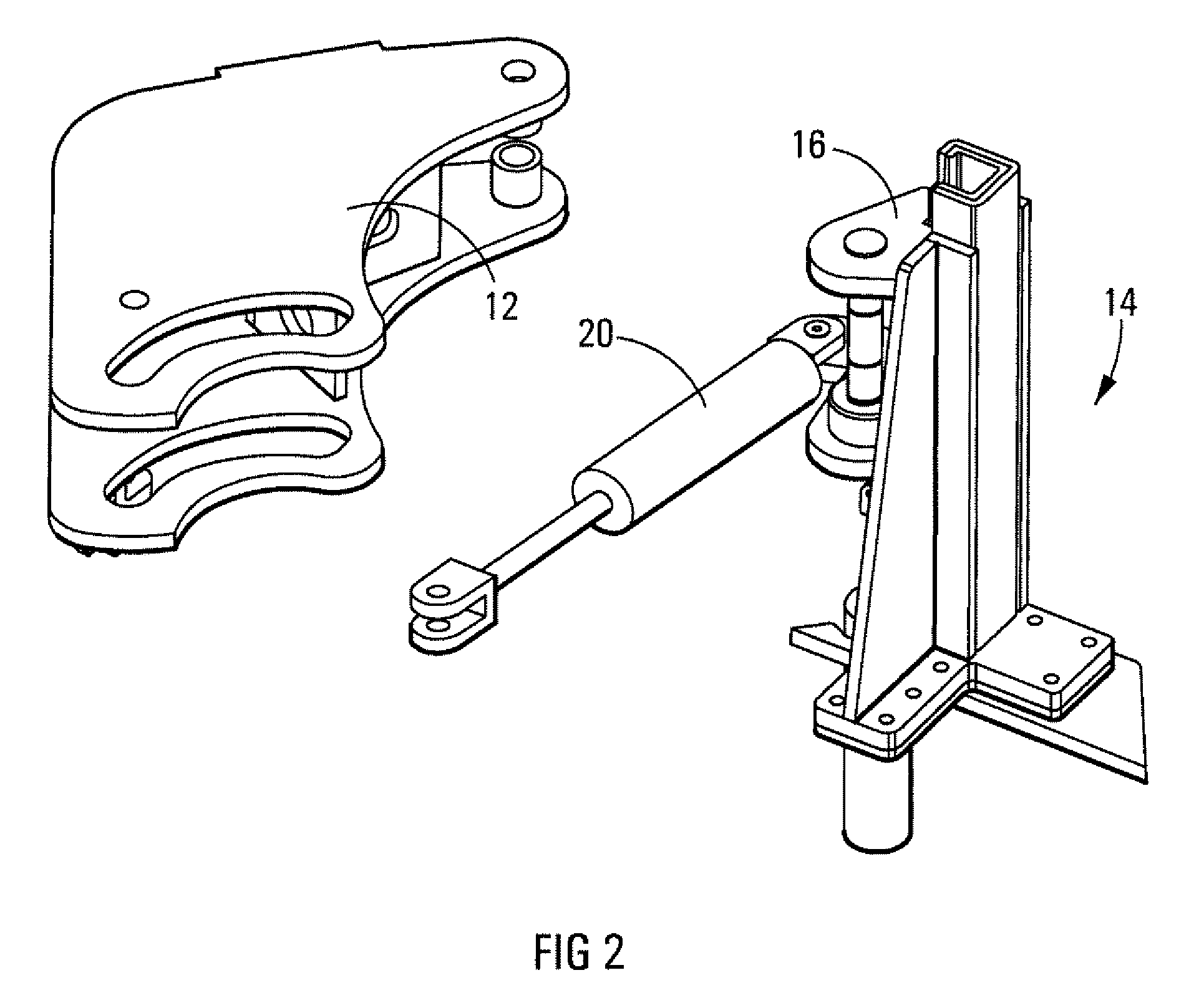
[0022]Referring initially to FIGS. 1 to 8 of the drawings, a drill bit wrench for use with drilling apparatus, in accordance with the invention, is designated generally by the reference numeral 10. The drill bit wrench 10 includes a carrier member 12 that, in the operative configuration of the drill bit wrench with respect to a drilling apparatus, is pivotally mounted on the support structure 14 of the drilling apparatus, typically via a mounting structure including a mounting bracket 16, which may form a part of the drill bit wrench. The support structure of the drilling apparatus clearly is only partially shown. The carrier member is pivotally displaceable about a pivot axis 18 by the operation of a first hydraulically operable piston / cylinder mechanism 20, the mechanism 20 being operable between a location 22 on the bracket 16 and a location 24 on the carrier member 12, as shown. The pivotal displacement of the carrier member 12 with respect to the support structure 14 by the ope...

second embodiment

[0032]Referring now to FIGS. 16 to 18 of the drawings, a drill bit wrench for use with drilling apparatus, in accordance with the invention, is designated generally by the reference numeral 80. The construction of the drill bit wrench 80 is essentially equivalent to that of the drill bit wrench 10 and like parts of the drill bit wrench 80 is thus designated by the same reference numerals as before.

[0033]As is clearly apparent from FIGS. 17 and 18 of the drawings, the drill bit wrench 80 is particularly configured to be mounted on a support post of the support structure of a drilling apparatus that is disposed “on the opposite side of the drill bit of the apparatus”, thus requiring the rotational displacement of the gripping member of the drill bit wrench to be suitably adapted for loosening of a drill bit segment. The operation of the drill bit wrench 80 and particularly the rotational displacement of the gripping member thereof for loosening a drill bit segment is clearly illustrat...


PUM


Abstract

The invention relates to a drill bit wrench (10) for use on a drilling apparatus for loosening a drill bit segment of a drill bit during drilling of holes into the ground. The wrench includes a carrier member (12) operatively supported on the drilling apparatus. A gripping member (26) is displaceably located on the carrier member and a lever arm (38) is pivotally located on the gripping member, displacement mechanisms (20, 34, 42) providing for required displacement of the parts of the wrench for its operation. One displacement mechanism (42) provides for an initial direct gripping force to be applied on a drill bit segment, which force is sufficient to permit loosening of the segment in normal circumstances, an additional gripping force, to be induced by a wedging action of a wedge face of the lever arm, being provided for, where required.

Description

FIELD OF INVENTION[0001]This invention relates to a wrench for use with drilling apparatus.[0002]The invention relates particularly to a wrench for use with drilling apparatus used for drilling holes into the ground with a drill bit comprising a drilling segment, extension segments and a distance piece, the distance piece, in use, being engaged by the drilling apparatus, thereby to connect the drill bit to the drilling apparatus. The above segments of a drill bit are hereinafter referred to merely as drill bit segments.BACKGROUND TO INVENTION[0003]As part of a drilling operation, extension segments of a drill bit must be located in line with or removed from a drill bit, which requires adjacent segments of a drill bit, connected via complementary threads in a spigot and socket fashion, to be loosened with respect to one another. Insofar as the thread configuration of drill bit segments of a drill bit provide for segments to be tightened together during drilling, a wrench, referred to...

Claims


Application Information

Patent Timeline
Patent Type & Authority Applications(United States)
IPC IPC(8): B25B13/50
CPCE21B19/163
Inventor GOUWS, PETRUS CHRISTIAAN
Owner GOUWS PETRUS CHRISTIAAN
Why Eureka
Try Eureka