Hydrocarbon production system, method for performing clean-up and method for controlling flow

Inactive Publication Date: 2011-06-16
AKER SUBSEA AS
View PDF43 Cites 8 Cited by
  • Summary
  • Abstract
  • Description
  • Claims
  • Application Information

AI Technical Summary

Benefits of technology

[0021]In a second aspect of the present invention, a method is provided for performing clean-up of a subsea well and a subsea production module in a hydrocarbon production system, the subsea production module being adapted to produce a fluid transmitted through a main flow path including a choke valve, wherein during clean-up a bypass connection is opened to direct the produced fluid and/or treatment fluid from the well to a bypass around the choke valve in order to prevent debris in the flow from damaging or blocking the choke valve.
[0022]The producing module produces a clean-up fluid comprising debris during the cleaning up, and the clean-up fluid is transmitted through the main flow path. A bypass connection directs the clean-up fluid through a bypass line arranged in parallel to the choke valve to prevent malfunction and blockage of the choke valve due to the fluid comprising debris.
[0023]In a third aspect of the invention it relates to a method for controlling the flow in a hydrocarbon production system comprising a subsea production module, operatively connected to a subsea well, a subsea recei

Problems solved by technology

This complex clean-up product comprising debris provides a substantial risk of choke malfunction and blockage when transported through the choke valve.
On the other hand, no existing choke valve vendor can or will give a guarantee that the choke can tolerate this, as it is almost impossible to know what type debris will flow through the choke and what dimension the debris will have.
But still it will always be a risk for blockage of trim ports in the choke valve.
Both good controllability and maximum flow are featu

Method used


Image

  • Hydrocarbon production system, method for performing clean-up and method for controlling flow
  • Hydrocarbon production system, method for performing clean-up and method for controlling flow

Examples


Embodiment Construction

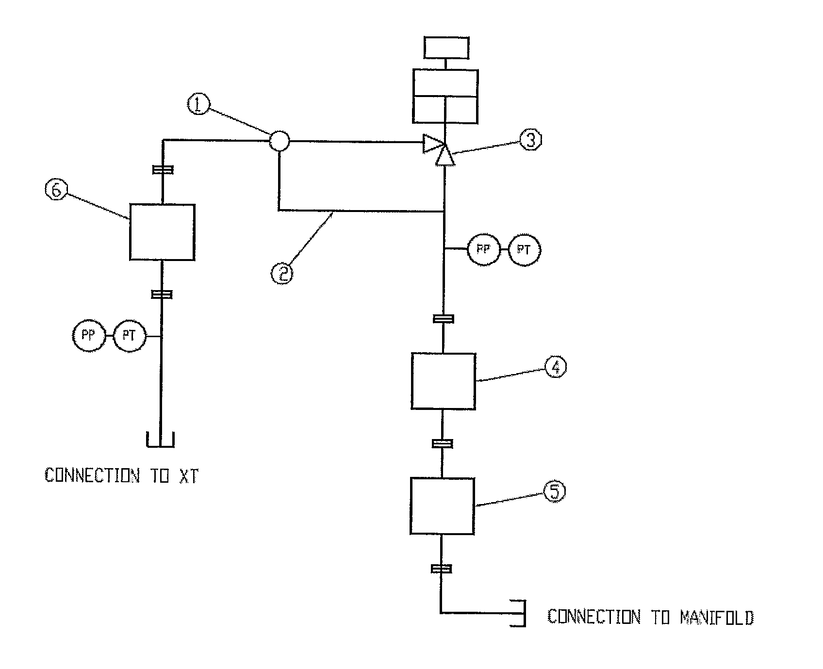
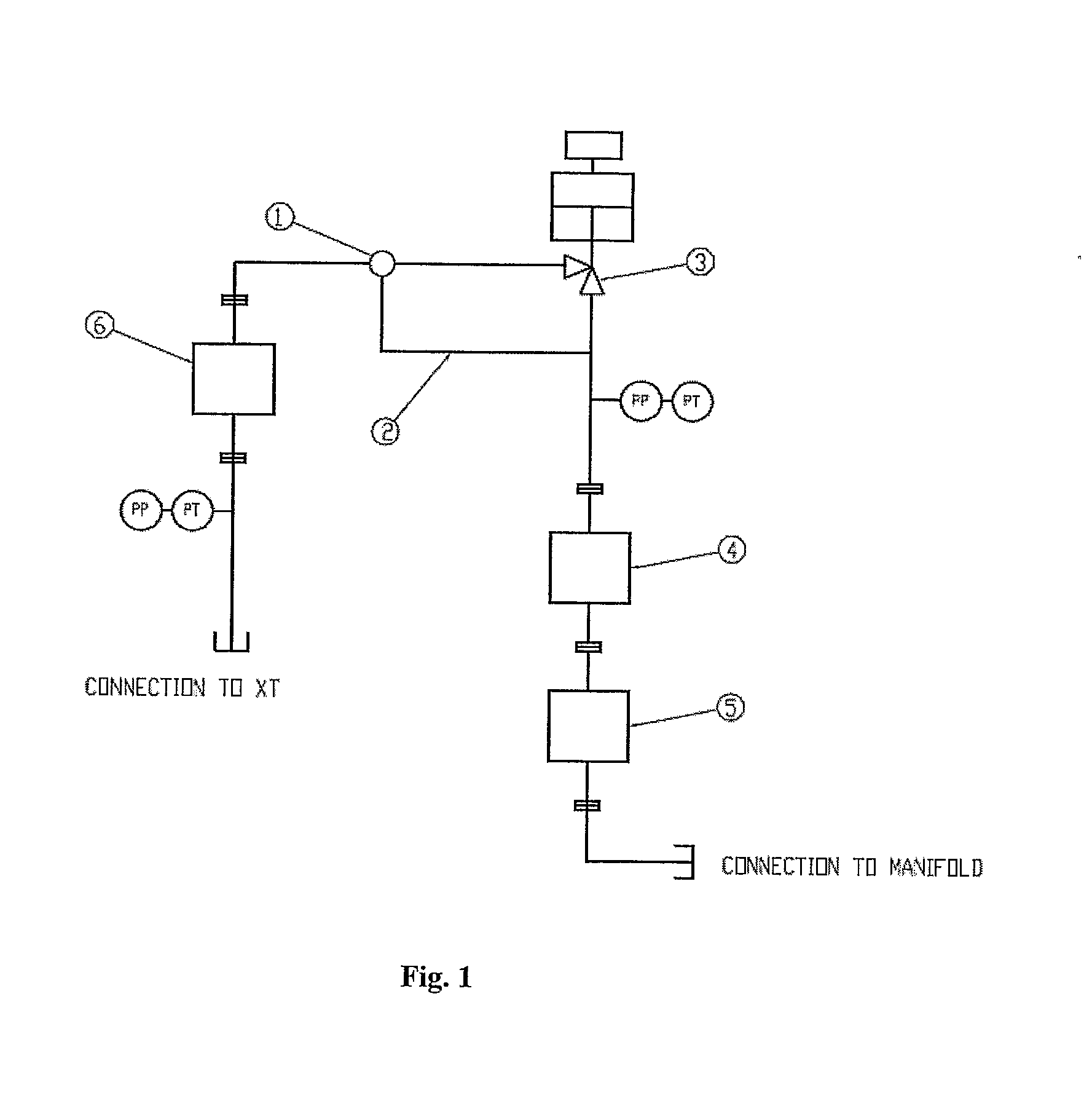
[0026]As seen in FIG. 1, a pipeline 7 has a connection to a Xmas Tree and a subsea well (commonly denoted by reference numeral 8) in one end, and the pipeline 7 is connected to a manifold 9 at the other end. A choke valve 3 for controlling the flow through the pipeline 7 is connected between the two end points 8, 9 of the line 7. For illustration purposes only, typical building blocks are also shown in FIG. 1. Such building blocks can be a flow meter 4, sand sensor 5 and injection line 6. Pressure and temperature sensors PP, PT are also inserted in the pipeline 7. In regular operation of the system seen in FIG. 1, fluid from the subsea well flows from the Xmas tree 8 through the choke valve 3 to the manifold 9. During a clean-up process of the subsea well or Xmas Tree 8 the choke valve 3 can not safely handle the debris in the fluid. Thus a bypass line 2 is implemented as an additional line 2, in parallel with the choke valve 3 to prevent the choke valve 3 from being damaged by debr...


PUM


Abstract

The present invention relates to a device for transmitting fluid from a subsea producing module (8) to a subsea receiving module (9) comprising a choke valve (3) in a main flowpath (7) of the fluid. A bypass line (2) is arranged in parallel to the choke valve (3) and the bypass line (2) is connected to the main flowpath (7) by a bypass connection (1).

Description

FIELD OF THE INVENTION[0001]The present invention relates to a hydrocarbon production system comprising a subsea well, a subsea production module, a subsea receiving module and a choke valve situated in a main flow path of production fluid from the well, between the production module and the receiving module.BACKGROUND OF THE INVENTION AND PRIOR ART[0002]In a subsea installation, several wells or Xmas Trees are connected to a common manifold. The pressures in these wells are different, and to be able to transmit oil or gas to the common manifold, the pressure needs to be substantially equal. Thus, a choke valve is installed between each Xmas Tree and the manifold to adjust and control the pressure.[0003]It is a standard procedure to perform a clean-up process in a Xmas Tree as a basis for commissioning. Traditionally, the clean-up is done through the choke valve. The product of the clean-up can be fluids with different viscosity, and it can also comprise different types and dimensio...

Claims


Application Information

Patent Timeline
IPC IPC(8): E21B34/04E21B34/00E21B33/035
CPCE21B43/01E21B43/12E21B43/017
Inventor SELSTAD, STIAN
Owner AKER SUBSEA AS
Why Eureka
Try Eureka