Air suspension

a technology of air springs and air tubes, which is applied in the direction of shock absorbers, mechanical devices, transportation and packaging, etc., can solve the problems of air spring components, air sleeve and/or air tube damage, and high risk of damage, so as to prevent damage and/or failure of components

Inactive Publication Date: 2011-06-16
HL MANDO CORP
View PDF10 Cites 16 Cited by
  • Summary
  • Abstract
  • Description
  • Claims
  • Application Information

AI Technical Summary

Benefits of technology

[0008]The present disclosure is directed to solving the problems of the related art, and an aspect of the present disclosure provides an improved air suspension that prevents damage and / or failure of components of an air spring, such as an air sleeve, by unwanted force or moment, such as rotational torque, applied to the air spring during vehicle traveling.
[0010]Each of the first and second bearings may be a thrust bearing. The first and second bearings, in particular, the first and second bearings employing the thrust bearings, may permit rotational movement of a damper side to counterbalance rotational moment of a kingpin axis, thereby preventing damage and / or failure of the air sleeve and / or an air tube.
[0011]The air suspension may further include a piston guide between the air piston and the cylinder. The piston guide may be made of a viscoelastic material, for example, urethane, and may serve to reduce a coning angle between the air piston and the cylinder.

Problems solved by technology

Conventionally, the air suspension has a problem in that components of the air spring, in particular, an air sleeve and / or an air tube, are highly susceptible to damage due to up-down movement, torsional rotation and an upward tilted angle (that is, coning angle) applied to the air spring during steering of the vehicle.
This problem is common to both a canister insert-molding integration type and a canister / upper mount separation type.
In the former case, for example, when steering a 5-link double wishbone type vehicle, the variation in kingpin axis causes the up-down movement, torsional rotation and coning angle in the air spring, so that cracks are formed on a damper bush and the air sleeve is damaged.
In the latter case, when steering the 5-link double wishbone type vehicle, the variation in kingpin axis causes the up-down movement, torsional rotation and coning angle in the air spring, so that torsional moment is generated between the upper mount and the canister, thereby damaging the air tube.

Method used


Image

  • Air suspension
  • Air suspension
  • Air suspension

Examples


Embodiment Construction

[0021]Hereinafter, exemplary embodiments of the present disclosure will be described in detail with reference to the accompanying drawings. The following embodiments are given by way of illustration to provide a thorough understanding of the invention to those skilled in the art. Hence, it should be understood that other embodiments will be evident based on the present disclosure, and that system, process or mechanical changes may be made without departing from the scope of the invention. Likewise, it should be noted that the drawings are not to precise scale and some of the dimensions, such as width, length, thickness, and the like, are exaggerated for clarity of description in the drawings. Like elements are denoted by like reference numerals throughout the specification and drawings.

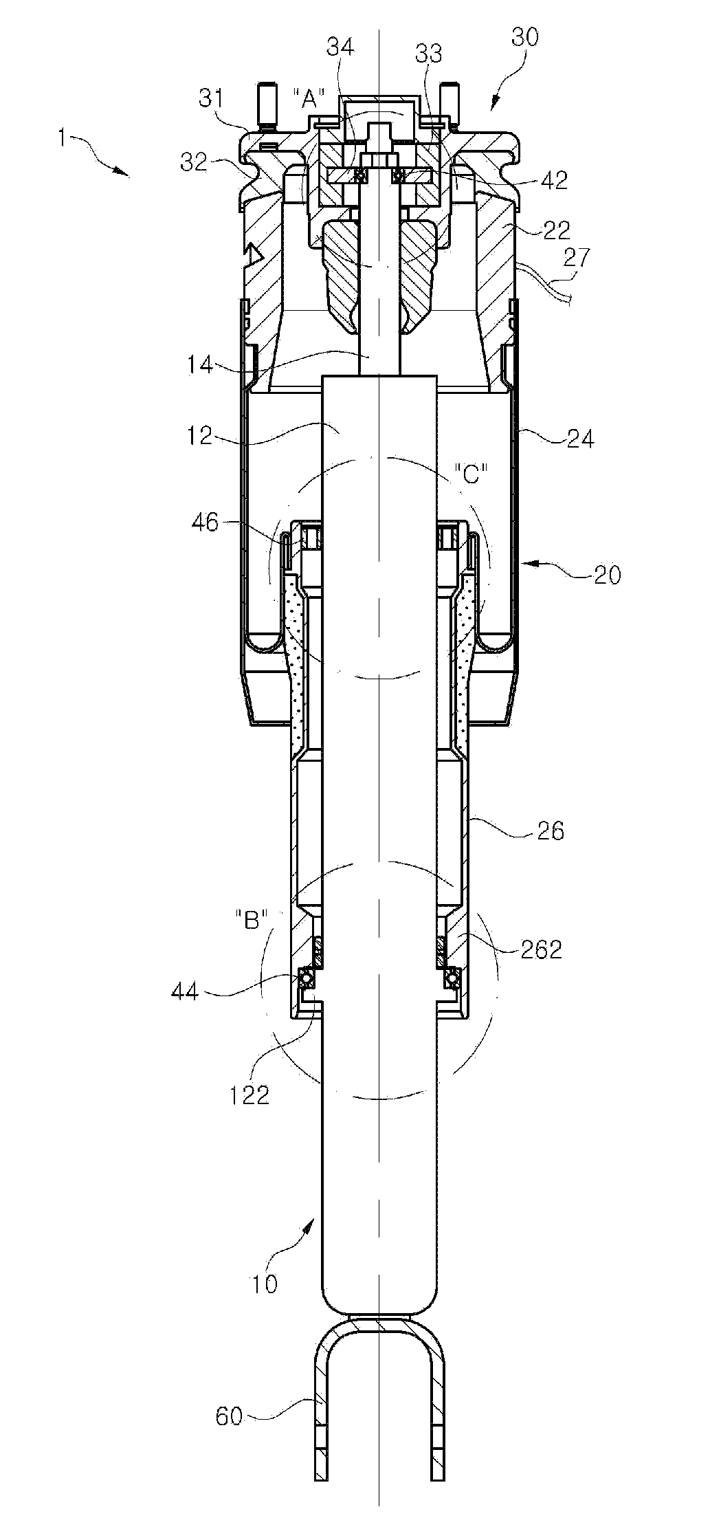
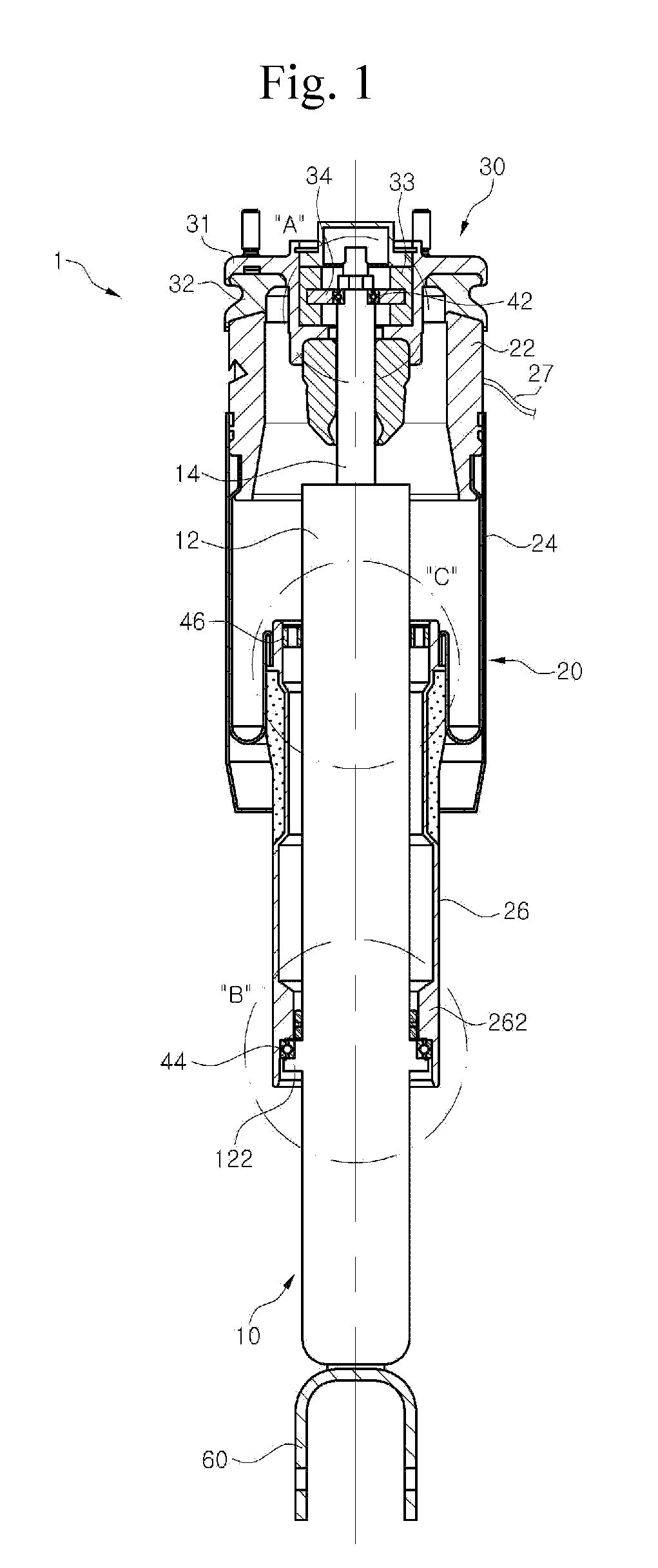
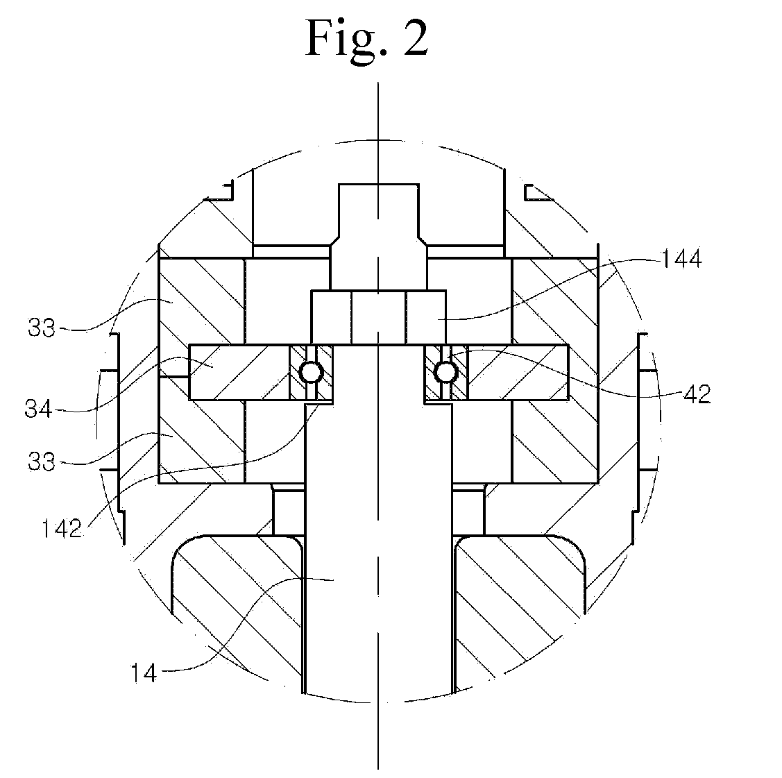
[0022]FIG. 1 is a side-sectional view of an air suspension in accordance with an embodiment, FIG. 2 is an enlarged view of part “A” of FIG. 1, FIG. 3 is an enlarged view of part “B” of FIG. 1, and FIG...


PUM


Abstract

Disclosed is an improved air suspension that prevents damage and / or failure of a component of an air spring, such as an air sleeve, by unwanted force or moment, such as rotational torque, applied to the air spring during vehicle traveling. The air suspension includes a damper including a cylinder and a piston rod, an air spring to which a canister and an air piston are hermetically connected via an air sleeve, an upper mount which secures the piston rod and the canister to a vehicle frame, a first bearing disposed at a connecting portion between the upper mount and the piston rod, and a second bearing disposed at a connecting portion between the air piston and the cylinder. Each of the first and second bearings is a thrust bearing.

Description

BACKGROUND[0001]1. Technical Field[0002]The present disclosure relates to an air suspension including a damper and an air spring, and, more particularly, to an air suspension which includes an improved structure to prevent damage of a component of an air spring, in particular, an air sleeve.[0003]2. Description of the Related Art[0004]In general, a suspension is disposed between a vehicle frame and wheels, and includes springs and dampers, that is, shock absorbers. The suspension using air springs as the springs is referred to as an “air suspension”. The air suspension includes an upper mount for securing both the damper and air spring to the vehicle frame.[0005]The damper includes a cylinder and a piston rod. The cylinder has a space filled with an operating fluid, such as an oil, inside a tube. A piston valve is disposed in the tube to generate damping force in cooperation with the operating fluid. Since the piston valve is connected to a piston rod, the piston valve generates the...

Claims


Application Information

Patent Timeline
Patent Type & Authority Applications(United States)
IPC IPC(8): B60G15/12F16F9/04
CPCB60G15/12F16F9/54F16F9/0454B60G13/10F16F9/34
Inventor KWON, BYUNG SOO
Owner HL MANDO CORP
Why Eureka
Try Eureka