Increased frequency power generation using low-frequency ambient vibrations

a technology of ambient vibration and increased frequency, applied in the direction of mechanical energy handling, generator/motor, dynamo-electric components, etc., can solve the problems of resonance-based generators, need to be tuned, and not desirable for some applications

Active Publication Date: 2011-06-16
RGT UNIV OF MICHIGAN
View PDF9 Cites 31 Cited by
  • Summary
  • Abstract
  • Description
  • Claims
  • Application Information

AI Technical Summary

Benefits of technology

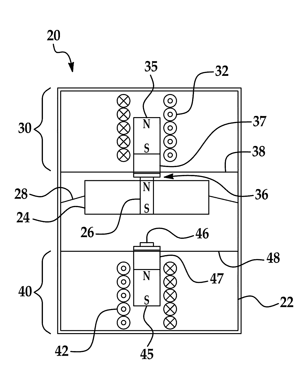
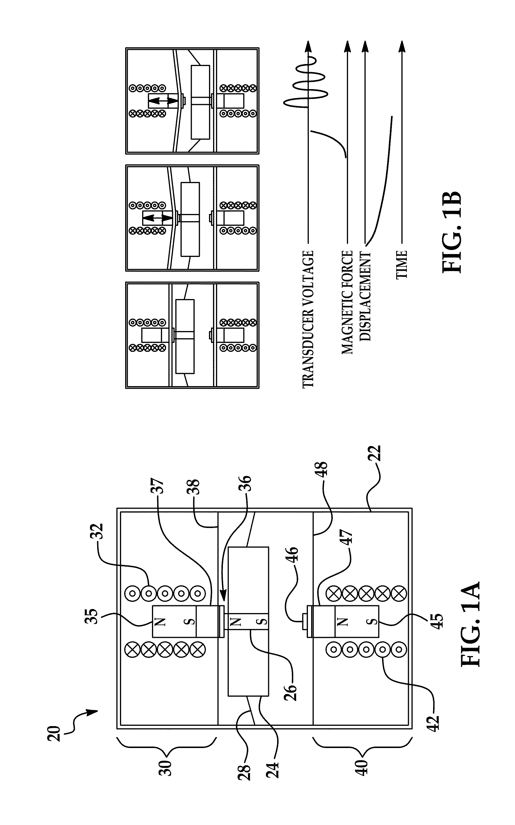
[0007]In accordance with another embodiment of the invention, there is provided an increased frequency power generator which includes a housing, an inertial mass mounted in the housing, and first and second transducers mounted in the housing. The inertial mass is capable of at least limited movement within the housing in response to low frequency vibration of the housing. The first transducer is positioned within the housing adjacent a first side of the inertial mass and the second transducer is positioned within the housing adjacent a second side of the inertial mass, wherein the inertial mass is suspended within the housing between the first and second transducers such that

Problems solved by technology

Although electrochemical batteries and fuel cells can provide more power, they are not desirable for some applications due to their limited lifetime, size, and/or weight.
The use of resonance-based generators

Method used


Image

  • Increased frequency power generation using low-frequency ambient vibrations
  • Increased frequency power generation using low-frequency ambient vibrations
  • Increased frequency power generation using low-frequency ambient vibrations

Examples


embodiment 60

[0041]FIG. 8(b) is a modified embodiment 60 wherein the mass 64 is attached to a beam 65 such that the overall mechanical structure has an eccentric center of mass. The beam 65 is either supported on the housing 62 using a hinge or a bearing 67 and able to rotate around its base. The configuration presented in FIG. 8(b) is suitable for non-linear vibration.

embodiment 70

[0042]FIG. 8(c) shows another embodiment 70, in which the IFPG is configured such that the transducers and the actuation mass do not move along a common axis or in the same plane. In other words the mass passes over or under one or both transducers and a suitable latching mechanism could be employed. The inertial mass mechanism in these three (and other) embodiments can be spring-loaded or not, and perhaps even submerged in a fluid which acts as the spring / support structure. The energy coupling between the mass and the transducer can be performed via mechanical latching / engagement such that as the mass moves past the transducer it physically pushes it into operation. Also, more or less transducers can be used than that shown.

[0043]Referring now to FIG. 9, there is shown a fourth embodiment 80 of an IFPG manufactured in a more miniaturized form factor. FIG. 10(a) shows a photograph of the manufactured device. The IFPG 80 has a housing 82 milled out of aluminum to leave a 1 mm thick s...


PUM


Abstract

An increased frequency power generator that includes a pair of transducers located on opposite sides of a suspended inertial mass. Magnetic attraction is used to couple the mass to each of the two transducers in alternating fashion in response to vibration and other movement externally imparted on the generator. Each transducer includes a suspended magnetic element that couples and decouples to the inertial mass as it reciprocates in the housing due to the applied external moving force. As the inertial mass decouples from one transducer on its way to magnetically connecting to the other transducer, the decoupled suspended magnetic element oscillates at a frequency greater than the imparting force, thereby generating electrical power.

Description

CROSS-REFERENCE TO RELATED APPLICATION[0001]This application claims the priority of U.S. Provisional Patent Application No. 61 / 218,656, filed Jun. 19, 2009, the contents of which are hereby incorporated by reference.STATEMENT REGARDING FEDERALLY SPONSORED RESEARCH[0002]This invention was made with government support under EEC-9986866 awarded by the National Science Foundation. The government has certain rights in the invention.TECHNICAL FIELD[0003]The invention relates generally to power scavenging and, more particularly, to electrical energy harvesting from low frequency ambient mechanical vibrations using a non-resonant electrical power generator.BACKGROUND OF THE INVENTION[0004]As the number and variety of microelectronic and other low power devices continues to grow, so too the need for sources of power to run these devices. Wireless sensors, implantable devices, and other low-power gadgets typically obtain operational power in one of two ways: 1) by using electrochemical batter...

Claims


Application Information

Patent Timeline
IPC IPC(8): H02K35/00H02N2/18H02N1/08
CPCH01L41/1134H02N2/186H02K35/02H01L41/12H10N30/00H10N30/304H10N35/00
Inventor GALCHEV, TZENOKIM, HANSEUPNAJAFI, KHALIL
Owner RGT UNIV OF MICHIGAN
Why Eureka
Try Eureka