Integrated, Lighted Ultrasonic Inserts

a technology of ultrasonic inserts and integrated components, which is applied in the field of switching a lighted insert, can solve problems such as illumination of the light source, and achieve the effects of convenient and convenient provision, convenient re-charge, and minimal fluctuations

Inactive Publication Date: 2011-06-16
HU FRIEDY MFG
View PDF31 Cites 4 Cited by
  • Summary
  • Abstract
  • Description
  • Claims
  • Application Information

AI Technical Summary

Benefits of technology

[0013]The embodiments of the present disclosure provide numerous benefits. For example, in the present disclosure, the light source is powered by an electrical power storage device or power pack and not by power delivered to the device itself. Thus, power fluctuations to the device do not affect the intensity of the light source at all. By using the electrical storage device, the light source generally may deliver a light at a steady, desired level of intensity with minimal fluctuations. Similarly, by using the electrical storage device, power fluctuations based on an integrity of a stack within a magnetostrictive device also do not affect light intensity. In some embodiments, the electrical storage device may be conveniently re-charged via induction.
[0014]Furthermore, the present disclosure allows the light source to be illuminated even when a tip of a magnetostrictive device is not moving. In fact, the present disclosure provides embodiments that allow a user to control whether the light source is on or off independently, from a user perspective, of whether or not the tip is activated.
[0015]Moreover, embodiments of the present disclosure allow the light source to be illuminated not via magnetostriction but via a permanent magnet or other magnetic element. With these and other embodiments, light may be conveniently and easily provided at sites where the presence of electrical cords may be cumbersome, inconvenient or even impossible.

Problems solved by technology

When the switch detects the magnetic field generated by the magnetostrictive device, the switch may cause a completion of an electrical connection between the electrical storage device and the light source, thus illuminating the light source.

Method used


Image

  • Integrated, Lighted Ultrasonic Inserts
  • Integrated, Lighted Ultrasonic Inserts
  • Integrated, Lighted Ultrasonic Inserts

Examples


Embodiment Construction

[0024]Although the following text sets forth a detailed description of numerous different embodiments, it should be understood that the legal scope of the description is defined by the words of the claims set forth at the end of this patent and equivalents. The detailed description is to be construed as exemplary only and does not describe every possible embodiment since describing every possible embodiment would be impractical. Numerous alternative embodiments could be implemented, using either current technology or technology developed after the filing date of the application for this patent, which would still fall within the scope of the claims.

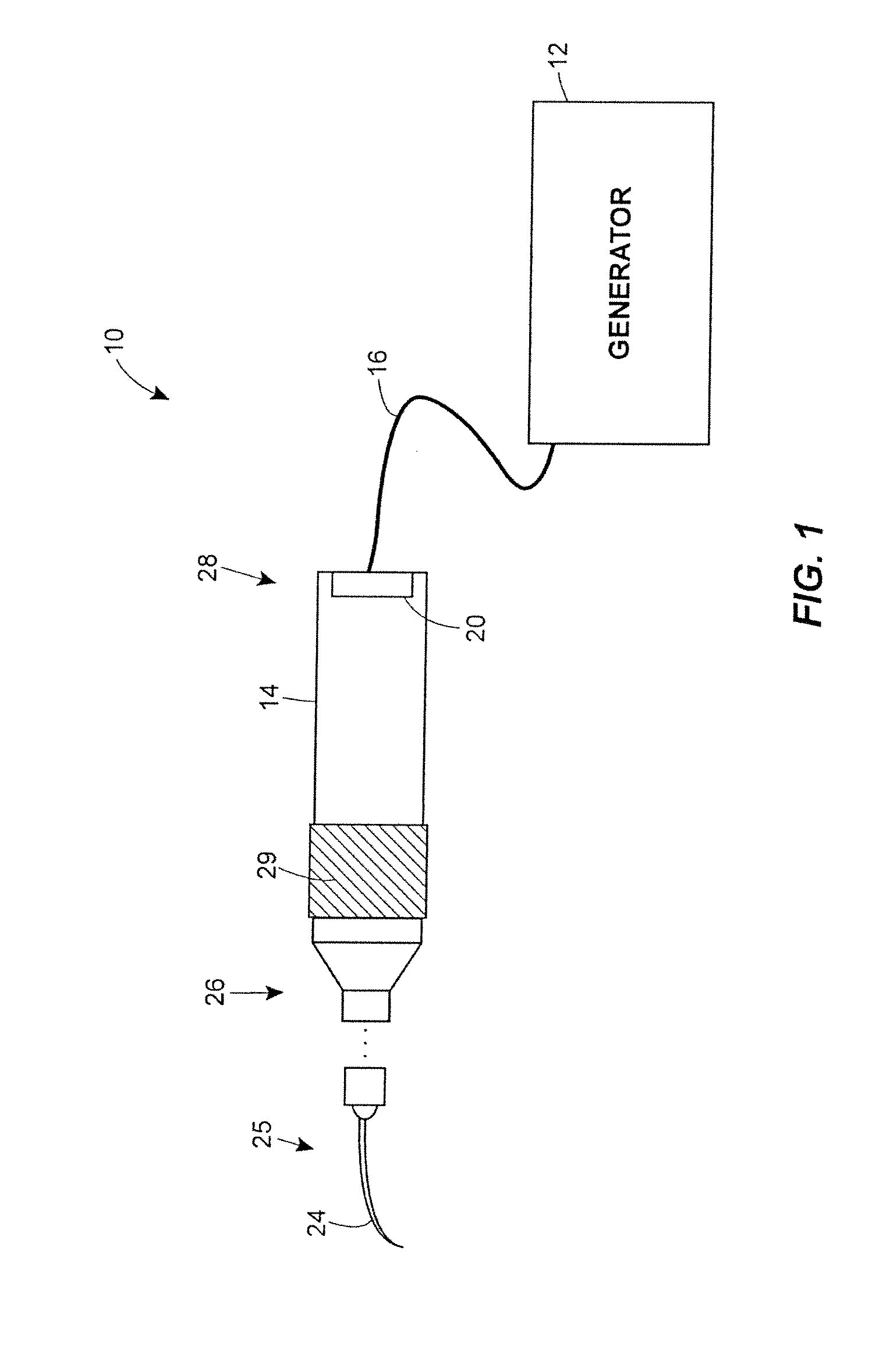
[0025]FIG. 1 illustrates an exemplary ultrasonic dental system 10. A dental practitioner may use the dental system 10 to remove calculi from a patient's teeth or to perform scaling, abrasion, or other similar dental procedures. In particular, a generator 12 may generate pulse width modulated (PWM) or alternating electric current (AC) at a ...


PUM

PropertyMeasurementUnit
magnetic fieldaaaaaaaaaa
resonant frequencyaaaaaaaaaa
frequencyaaaaaaaaaa

Abstract

Embodiments of a magnetostrictive device, a dental lighting system, a method of illuminating a lighting apparatus and a lighting apparatus are disclosed. The embodiments may include a lighting apparatus with a light source, an electrical power storage device and a switch. When the switch detects a magnetic field, the switch may complete an electrical connection between the electrical power storage device and the switch, thus illuminating the light source. The magnetic field may be magnetostrictively or non-magnetostrictively generated, and maybe be produced by a receptacle, a hand-piece or the lighting apparatus itself. A user may switch the light source on and off. In a magnetostrictive device, the light may be illuminated even when a tip is not activated, and the electrical power storage device may be inductively re-charged. The lighting apparatus may be included in an insert of a magnetostrictive device, such as a magnetostrictive ultrasonic hand-held dental device.

Description

BACKGROUND OF THE DISCLOSURE[0001]1. Field of the Disclosure[0002]This disclosure relates generally to integrating an electrical power source with a light source in an apparatus, and switching the light source on and off based on a magnetic field. Some embodiments of the disclosure relate to switching a lighted insert on and off in a magnetostrictive device such as a hand-held ultrasonic magnetostrictive dental device.[0003]2. Background Description[0004]Magnetostrictive ultrasonic dental hand-pieces are used in dentistry to remove calculus from teeth and perform other cleaning or abrasive operations by vibrating a metal insert at an ultrasonic frequency. A magnetostrictive ultrasonic dental hand-piece typically receives electric current having a controlled frequency from a generator and translates the received electrical energy into a mechanical motion of a tip of an insert coupled to the dental hand-piece. To this end, a magnetostrictive dental hand-piece includes an electrical co...

Claims


Application Information

Patent Timeline
Patent Type & Authority Applications(United States)
IPC IPC(8): H01F7/00
CPCH02J7/025H02J7/0044H02J50/12H02J2310/23A61C1/088
Inventor JAMNIA, MOHAMMAD A.
Owner HU FRIEDY MFG
Why Eureka
Try Eureka