Projected Capacitive Touch Panel

Inactive Publication Date: 2011-06-16
MINLEAD
View PDF3 Cites 21 Cited by
  • Summary
  • Abstract
  • Description
  • Claims
  • Application Information

AI Technical Summary

Benefits of technology

[0010]The primary objective of the present invention is to provide a projected capacitive touch panel with two substrates to avoid apexes caused at intersections of two conductive areas of different axes causing light interference and to prevent the apexes causing cracking due to environmental change, so prolonging lifetime of the projected capacitive touch panel in normal operation. To achieve the objective, the projected capacitive touch panel in accordance with the present invention comprises a lower substrate, an upper su

Problems solved by technology

Furthermore, the apexes may break when pressure and temperature are increased during transportation.

Method used


Image

  • Projected Capacitive Touch Panel
  • Projected Capacitive Touch Panel
  • Projected Capacitive Touch Panel

Examples


Embodiment Construction

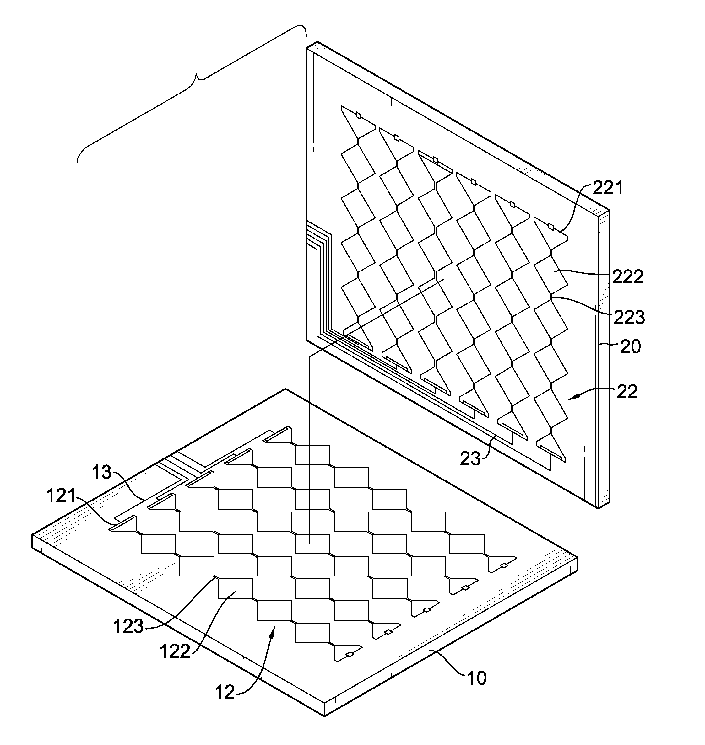
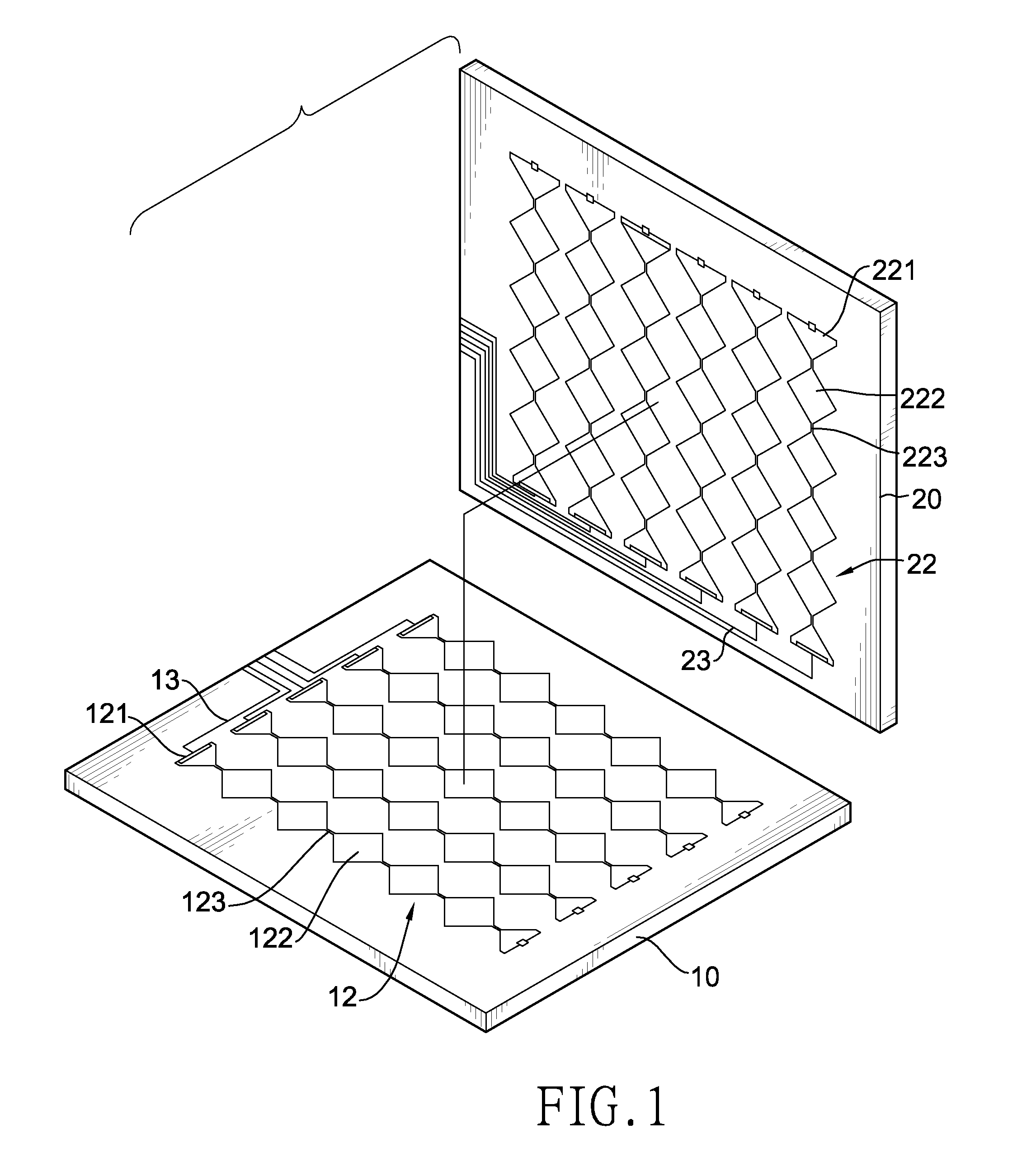
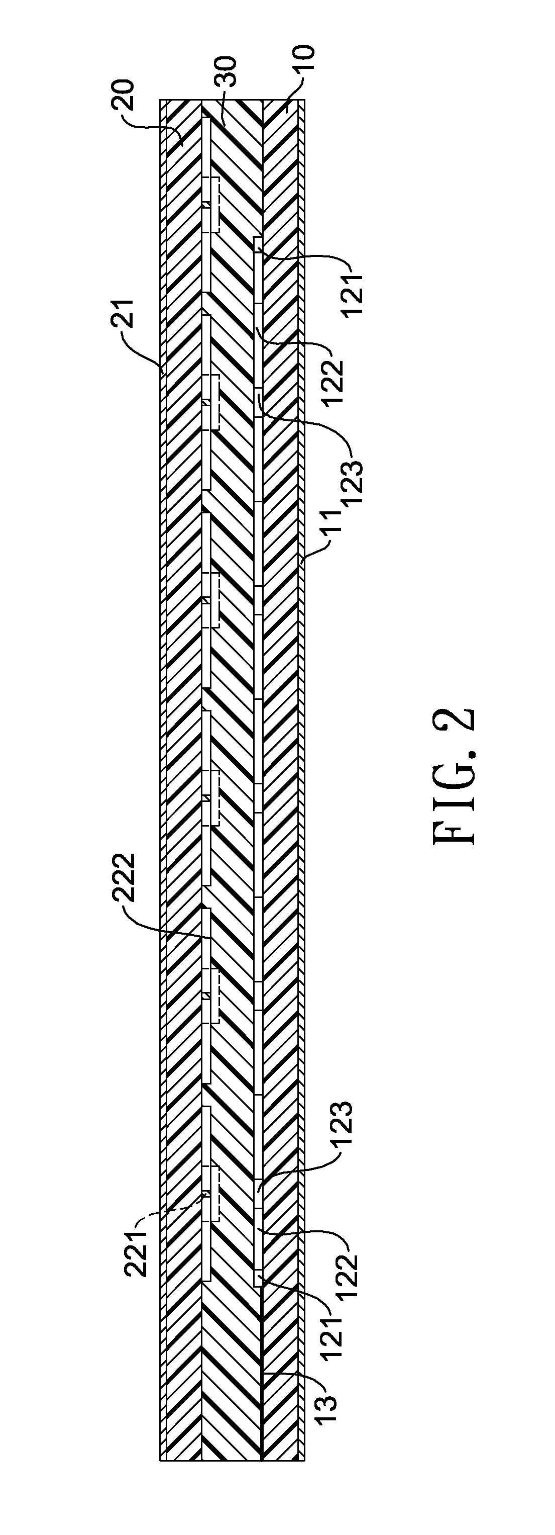
[0018]With reference to FIGS. 1, 2 and 3, a projected capacitive touch panel in accordance with the present invention has a lower substrate (10), an anti-electromagnetic interference (EMI) layer (11), an upper substrate (20), a protective layer (21) and an insulating adhesive layer (30).

[0019]The lower substrate (10) has an upper surface, a lower surface, a first-axial conductive area (12) and multiple conductive wires (13). The first-axial conductive area (12) is formed on the upper surface of the lower substrate (10) and has multiple conductive strips. The conductive strips are arranged in parallel in a first axis and each conductive strip has two ends, one port (121), multiple dots (122) and multiple connecting wires (123). The port (121) is formed on one of the ends of the conductive strip. The dots (122) may be made of indium tin oxide (ITO). Each connecting wire (123) is formed between two dots (122) and connects the dots (122) and may be made of ITO. The conductive wires (13)...


PUM


Abstract

A projected capacitive touch panel has a lower substrate, an upper substrate and an insulating adhesive layer. The lower substrate has a first-axial conductive area. The first-axial conductive area has multiple conductive strips arranged in parallel in a first axis. The upper substrate has a second-axial conductive area. The second-axial conductive area has multiple conductive strips arranged in parallel in a second axis different from the first axis. The insulating adhesive layer formed between the lower substrate and the upper substrate to adhere the lower substrate and the upper substrate. Two substrates respectively have conductive areas with different axes, so avoid formation of apexes and keep the substrates flat. Therefore, incident light of the projected capacitive touch panel is able to reflect evenly and avoid interference. The projected capacitive touch panel has stable quality and saves costs because no damage occurs during transportation.

Description

BACKGROUND OF THE INVENTION[0001]1. Field of Invention[0002]The present invention relates to a projected capacitive touch panel, and more particularly to a projected capacitive touch panel with two substrates to avoid apexes caused at intersections of two conductive areas of different axes causing light interference and to prevent the apexes causing cracking due to the environmental change, so prolonging lifetime of the projected capacitive touch panel during normal operation.[0003]2. Description of the Related Art[0004]Conventional touch panels include resistive touch panels, capacitive touch panels, acoustic wave touch panels and optical touch panels. Recently, capacitive touch panels have become more popular after Apple Computer, Inc. released iPod series and iPhone.[0005]Capacitive touch panels can be grouped into surface resistive touch panels (single-touch) and projected capacitive touch panel (multi-touch) and projected capacitive touch panel that was used in the iPod series ...

Claims


Application Information

Patent Timeline
IPC IPC(8): G06F3/044
CPCG06F2203/04107G06F3/044G06F3/0445G06F3/0446
Inventor HSU, JANE
Owner MINLEAD
Why Eureka
Try Eureka