Supercharge Your Innovation With Domain-Expert AI Agents!

Image encoding device

a technology of image encoding and encoding, applied in the field of image encoding technologies, can solve the problems of inability to reduce the redundancy of color signals and the method cannot be applied to still images, and achieve the effect of good accuracy

Active Publication Date: 2011-06-16
KDDI R&D LAB INC
View PDF8 Cites 8 Cited by
  • Summary
  • Abstract
  • Description
  • Claims
  • Application Information

AI Technical Summary

Benefits of technology

[0013]The present invention has been proposed in view of the above circumstances, and an object thereof is to provide an image encoding device for improving encoding efficiency by reducing an information amount of a signal to be predicted as a result of adaptively selecting a reference signal that is a reference from among a plurality of color signals obtained by separating an image and predicting another signal (signal to be predicted) from the reference signal.
[0014]To achieve the above-described object, in the present invention, at the time of encoding for each unit block by performing orthogonal conversion, quantization, and encoding on an intra-signal prediction residual signal obtained by performing difference processing on each pixel in a unit block configured by a plurality of pixels with each pixel that is intra-signal predicted, the intra-signal prediction residual signal in the unit block is separated into a plurality of signals configured by one reference signal and a signal to be predicted to thereby perform a signal-to-signal prediction, enabling reduction of redundancy of a color signal.

Problems solved by technology

On the other hand, a method for estimating a motion vector used in the motion compensation method enables reduction of the temporal redundancy; however, this method has a problem that the method cannot be applied to a still image.
The use of a combination of the above-described orthogonal conversion and quantization or the method for reducing spatial redundancy by the spatial prediction method can reduce the spatial redundancy within a frame; however, there is a problem that a different color signal in the same frame is independently processed, and thus, the redundancy of the color signal cannot be reduced.

Method used


Image

  • Image encoding device
  • Image encoding device
  • Image encoding device

Examples


Embodiment Construction

[0045]One example of an embodiment of an image encoding device according to the present invention will be explained with reference to FIG. 1 and FIG. 2.

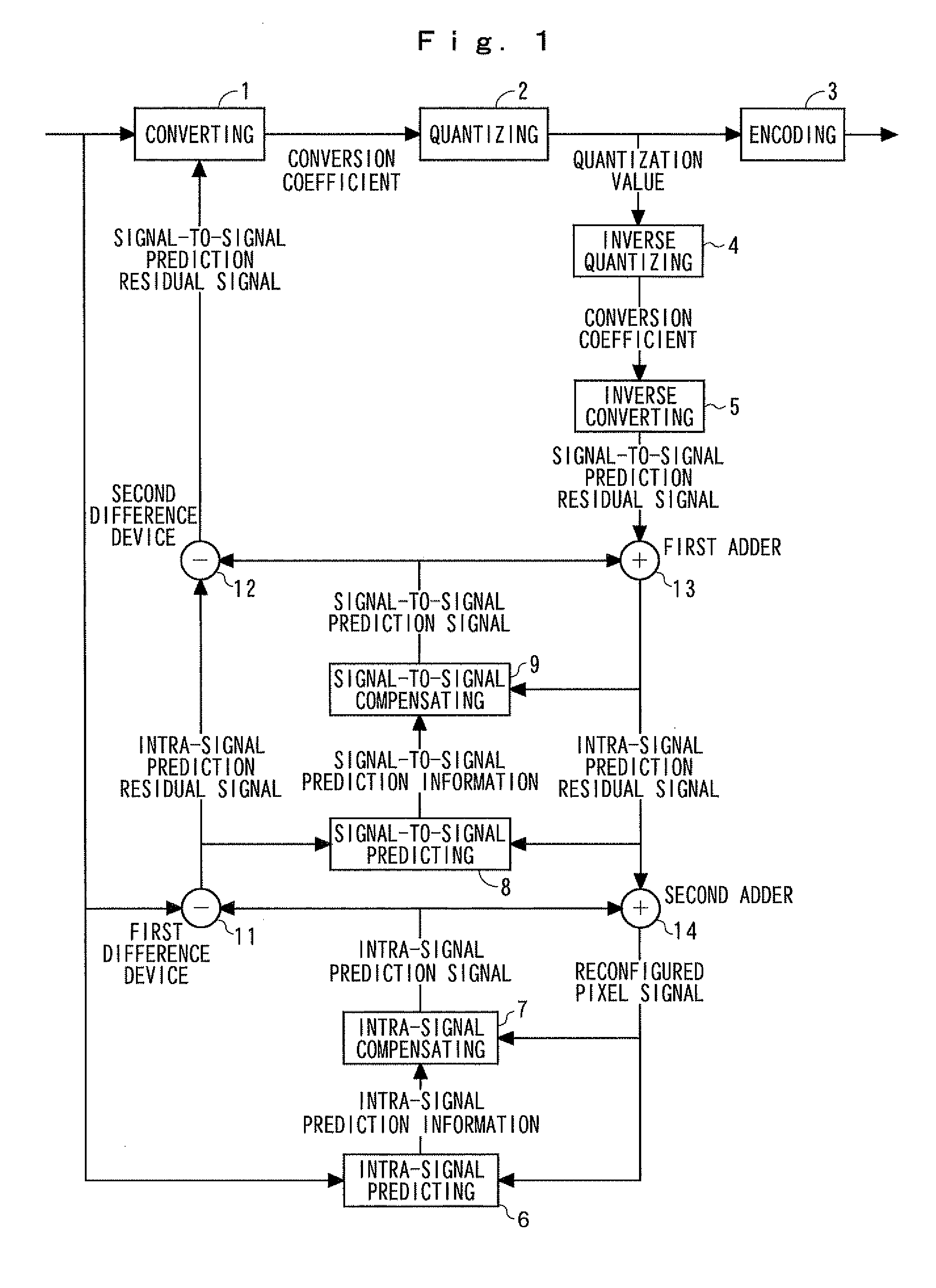
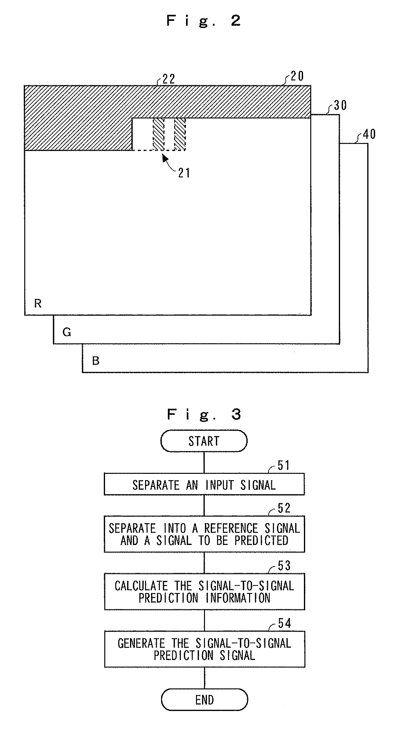
[0046]An image encoding device of the present invention is characterized in configuration by the addition of a function of predicting a signal between a plurality of signals by separating the intra-signal prediction residual signal in the unit block into a plurality of signals configured by one reference signal and a signal to be predicted, to the conventionally existing image encoding device in which encoding is performed for each unit block by performing orthogonal conversion, quantization, and encoding on an intra-signal prediction residual signal obtained by performing difference processing on each pixel in a unit block configured by a plurality of pixels with each pixel that is intra-signal predicted from an already-encoded pixel.

[0047]That is, as shown in FIG. 1, the conventional image encoding device includes: converting means...


PUM


Abstract

The image encoding device includes: signal-to-signal predicting means 8 for separating an intra-signal prediction residual signal obtained by performing difference processing between an input image signal and an intra-signal prediction signal into a reference signal and a signal to be predicted and calculating signal-to-signal prediction information used for performing signal-to-signal prediction on each pixel of the signal to be predicted corresponding to each pixel of the reference signal; and signal-to-signal compensating means 9 for obtaining a signal-to-signal prediction signal of the region to be encoded from a decoded intra-signal prediction residual signal and the signal-to-signal prediction information from the signal-to-signal predicting means, wherein each pixel of the signal to be predicted is encoded by performing orthogonal conversion, quantization, and encoding on the signal-to-signal prediction residual signal obtained by performing the difference processing between the intra-signal prediction residual signal and the signal-to-signal prediction signal.

Description

[0001]The present application is claims priority of Japanese Patent Application Serial No. 2009-281585, filed Dec. 11, 2009, the content of which is hereby incorporated by reference in its entirety.BACKGROUND OF THE INVENTION[0002]1. Field of the Invention[0003]The present invention relates to image encoding technologies when an image is compressed and encoded, and more particularly, relates to an image encoding device for predicting an object to be encoded from information correlated within the image so as to encode a prediction error to thereby serve to improve encoding efficiency.[0004]2. Description of the Related Art[0005]There has been a method for reducing temporal redundancy and a method for reducing spatial redundancy as a method for improving encoding efficiency in the conventional image encoding.[0006]A frame difference method or a motion compensation method is employed as a method for reducing temporal redundancy. In the frame difference method, a simple subtraction betw...

Claims


Application Information

Patent Timeline
Patent Type & Authority Applications(United States)
IPC IPC(8): G06K9/36H04N19/50H04N11/04H04N19/103H04N19/146H04N19/147H04N19/154H04N19/176H04N19/186H04N19/503H04N19/593H04N19/60H04N19/61H04N19/91
CPCH04N19/105H04N19/176H04N19/147H04N19/186H04N19/11H04N19/136H04N19/61
Inventor KATOU, HARUHISANAITOU, SEI
Owner KDDI R&D LAB INC
Features
  • R&D
  • Intellectual Property
  • Life Sciences
  • Materials
  • Tech Scout
  • Unparalleled Data Quality
  • Higher Quality Content
  • 60% Fewer Hallucinations
Learn More