Ultrasonic wave control device and recording material determining device

a technology of ultrasonic wave control and recording material, which is applied in the direction of instruments, electrographic processes, magnetic property measurements, etc., can solve the problems of difficult determination of paper type, and inability to optimize the driving signal controlled without recording material being placed

Active Publication Date: 2011-06-16
CANON KK
View PDF11 Cites 13 Cited by
  • Summary
  • Abstract
  • Description
  • Claims
  • Application Information

AI Technical Summary

Benefits of technology

[0006]The invention according to the present invention has been made in view of the above-described circumstances, and an object thereof is to appropriately control driving signals in accordance with a recording material and to output ultrasonic waves in accordance with the recording material.

Problems solved by technology

However, since driving signals are controlled with no recording material being placed, the driving signals controlled with no recording material being placed are not necessarily optimized for detecting a basis weight in a case where basis weights of various recording materials, such as thin paper having a small basis weight to thick paper having a large basis weight, are to be detected.
For example, assume that a driving signal that is adjusted with no recording material being placed is suitable for detecting a basis weight of ordinary paper, then a small output value is obtained in a recording material that is so-called thick paper having a basis weight of 120 g / m2 or more, which causes the possibility of determination of the type of paper being difficult.
Also, a large output value is obtained in a recording material that is so-called thin paper having a basis weight of 75 g / m2 or less and the output value is saturated, which causes the possibility of determination of the type of paper being difficult.

Method used


Image

  • Ultrasonic wave control device and recording material determining device
  • Ultrasonic wave control device and recording material determining device
  • Ultrasonic wave control device and recording material determining device

Examples


first embodiment

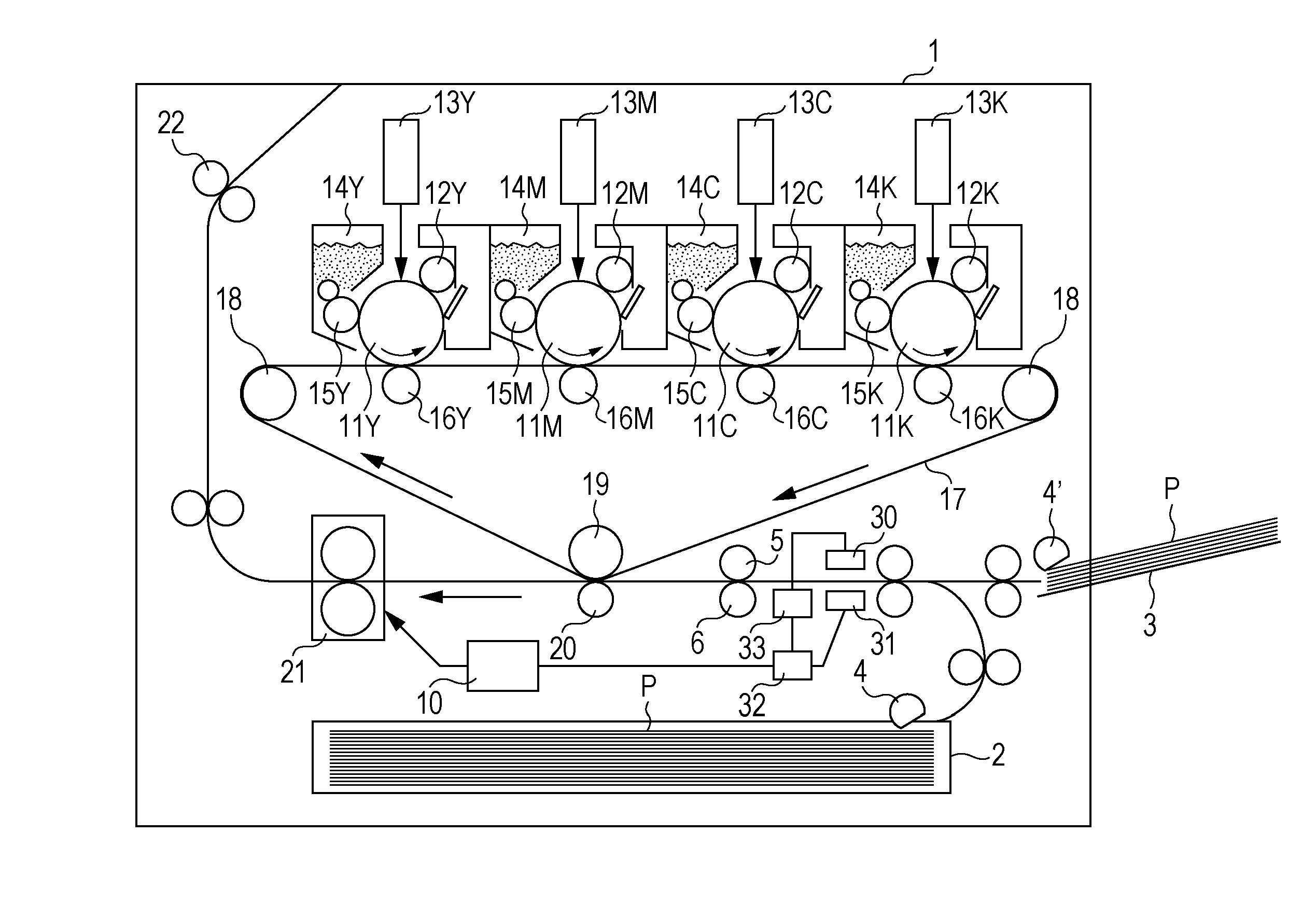
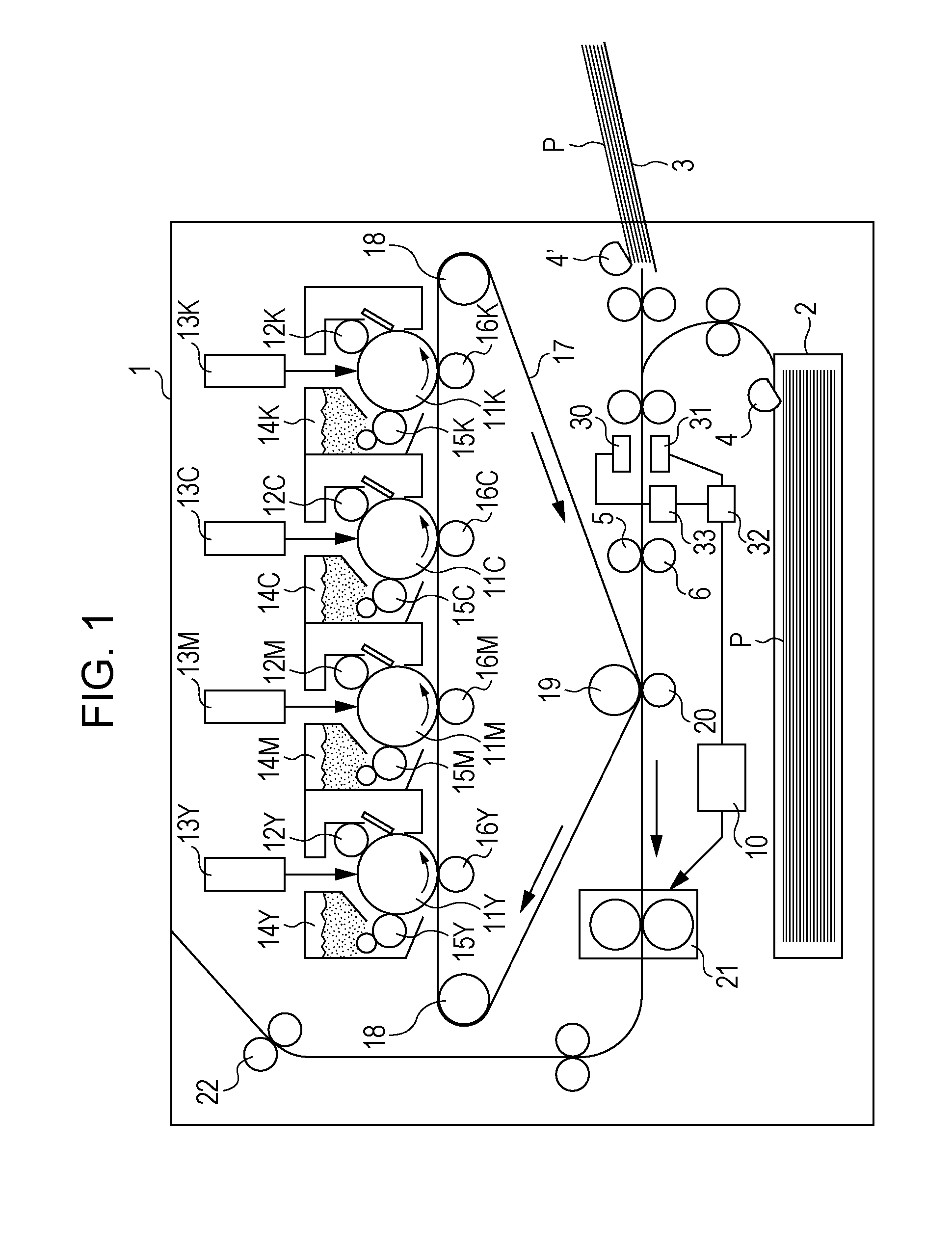
[0025]An ultrasonic wave control device and a recording material determining device according to this embodiment can be used in an image forming apparatus, such as a copying machine or a printer, for example. FIG. 1 is a configuration diagram illustrating an image forming apparatus as an example that adopts an intermediate transfer belt and that includes a plurality of image forming units arranged in parallel.

[0026]The configuration of the image forming apparatus 1 in FIG. 1 is as follows. Reference numeral 2 denotes a paper feed cassette that accommodates a recording material P. Reference numeral 3 denotes a paper feed tray on which a recording material P is loaded. Reference numeral 4 denotes a paper feed roller that feeds a recording material P from the paper feed cassette 2. Reference numeral 4′ denotes a paper feed roller that feeds a recording material P from the paper feed tray 3. Reference numeral 5 denotes a conveying roller that conveys a recording material P fed thereto, ...

second embodiment

[0059]In the first embodiment, a description has been given about a method for controlling a driving signal using a result of an initial measurement. In this embodiment, a description will be given about a method for detecting a multi-feeding state of a recording material P using a result of an initial measurement. Note that a description about the same things as those in the first embodiment, such as the configurations of the image forming apparatus 1 and the ultrasonic wave control device and the definition of a driving signal, is omitted here.

[0060]An operation of detecting multi-feeding in this embodiment will be described with reference to the flowchart in FIG. 10. In this flowchart, sequences S200 to S203 and sequences S206 to S214 are similar to sequences S100 to S112 in the flowchart in FIG. 6 of the foregoing first embodiment, and thus the description thereof is omitted here.

[0061]In sequence S204, the control unit 10 compares the received voltage value obtained in sequence...


PUM

PropertyMeasurementUnit
frequencyaaaaaaaaaa
sizeaaaaaaaaaa
voltageaaaaaaaaaa

Abstract

In a device for detecting a basis weight of a recording material, an initial measurement is performed by using ultrasonic waves that have passed through the recording material, and the recording material is roughly classified first. By changing the number of pulses of the driving signal in accordance with a result of the initial measurement, the basis weight of the recording material can be detected by using ultrasonic waves suitable for the recording material, so that the detection accuracy of the basis weight of the recording material can be increased.

Description

[0001]This application is a Continuation of International Application No. PCT / JP2009 / 070857, filed Dec. 14, 2009, which is hereby incorporated by reference herein in its entirety.TECHNICAL FIELD[0002]The present invention is an invention related to an ultrasonic wave control device that controls drive of ultrasonic waves and to a recording material determining device provided with the ultrasonic wave control device.BACKGROUND ART[0003]In a conventional image forming apparatus, the type of recording material (hereinafter also referred to as the type of paper) is set by a user with a setting using a computer or the like serving as an external apparatus or an operation panel provided in a main body of the image forming apparatus. In order to reduce burdens of such a user setting made from a computer or operation panel, an image forming apparatus that includes a sensor or the like serving as a determining device for determining the type of paper and that has a function of automatically ...

Claims


Application Information

Patent Timeline
Patent Type & Authority Applications(United States)
IPC IPC(8): G01N29/04G03G15/00
CPCG03G15/5029
Inventor NAKAMURA, TOMOHARUMATSUI, NORIOKOYAMA, SHOICHIISHIDA, TSUTOMUEBIHARA, SHUN-ICHI
Owner CANON KK
Why Eureka
Try Eureka