Wind turbine blades with controllable aerodynamic vortex elements

a technology of aerodynamic vortex and turbine blades, which is applied in the direction of wind energy generation, machines/engines, air-flow influencers, etc., can solve the problems of increasing drag force, limited versatility of elements for varying airflow conditions, and minimal usefulness of elements in “at rest” sta

Active Publication Date: 2011-06-16
GENERAL ELECTRIC CO
View PDF24 Cites 42 Cited by
  • Summary
  • Abstract
  • Description
  • Claims
  • Application Information

AI Technical Summary

Benefits of technology

Aspects and advantages of the invention will be set forth in part in the following description, or may be obvious from the description, or may be learned through practice of the invention.

Problems solved by technology

The detached-flow region also leads to an increase in drag force, mainly due to a pressure difference between the upstream attached-flow region and the downstream detached-flow region.
The vortex elements in these references have a defined shape, size, and configuration that does not change and, thus, the versatility of the elements for varying airflow conditions is limited.
Although the vortex generators discussed in the references cited above may be considered “dynamic” in that they are deployed to an active state, the usefulness of the elements in the “at rest” state is minimal.

Method used


Image

  • Wind turbine blades with controllable aerodynamic vortex elements
  • Wind turbine blades with controllable aerodynamic vortex elements
  • Wind turbine blades with controllable aerodynamic vortex elements

Examples


Embodiment Construction

Reference now will be made in detail to embodiments of the invention, one or more examples of which are illustrated in the drawings. Each example is provided by way of explanation of the invention, not limitation of the invention. In fact, it will be apparent to those skilled in the art that various modifications and variations can be made in the present invention without departing from the scope or spirit of the invention. For instance, features illustrated or described as part of one embodiment can be used with another embodiment to yield a still further embodiment. Thus, it is intended that the present invention include such modifications and variations as come within the scope of the appended claims and their equivalents.

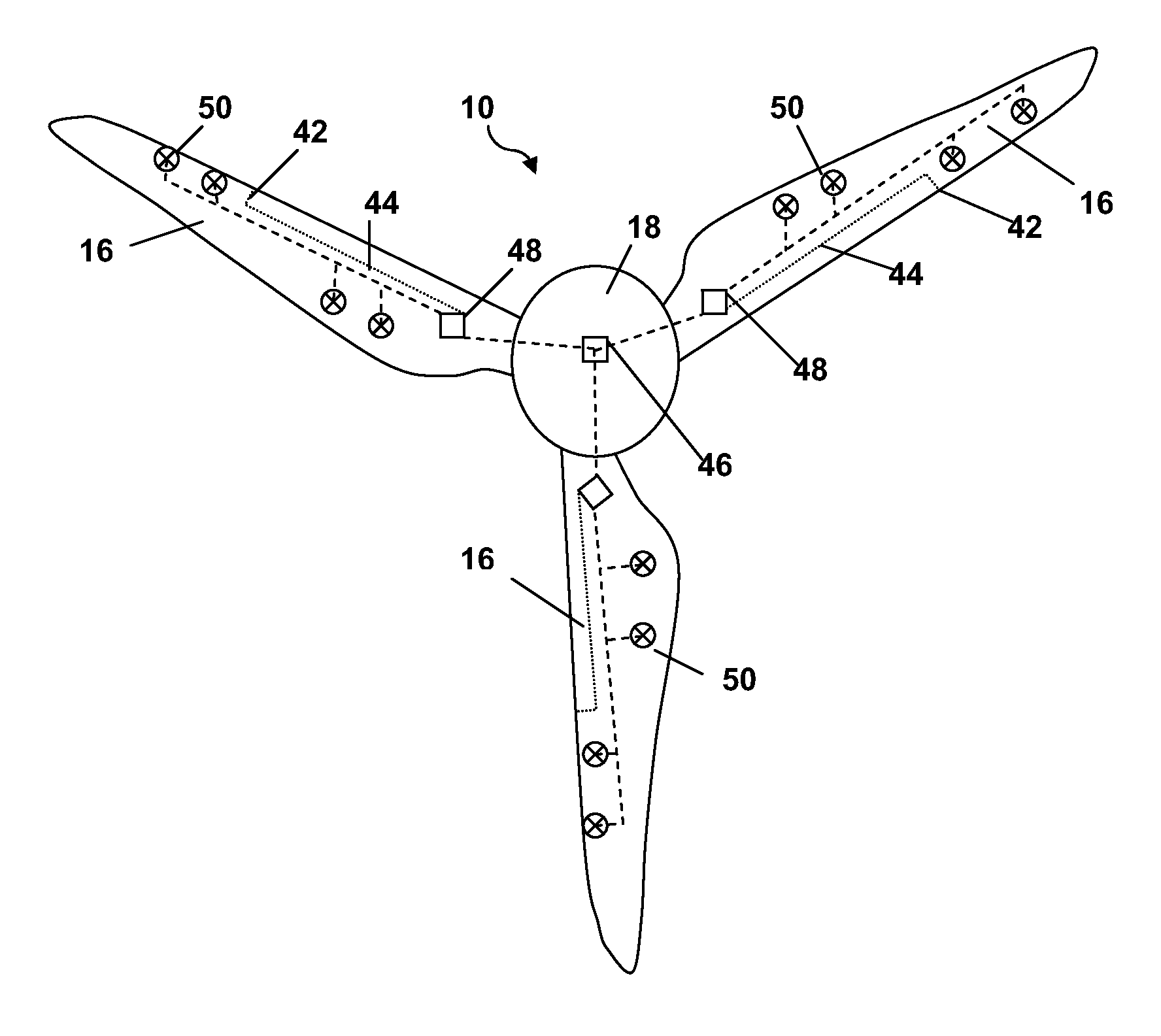
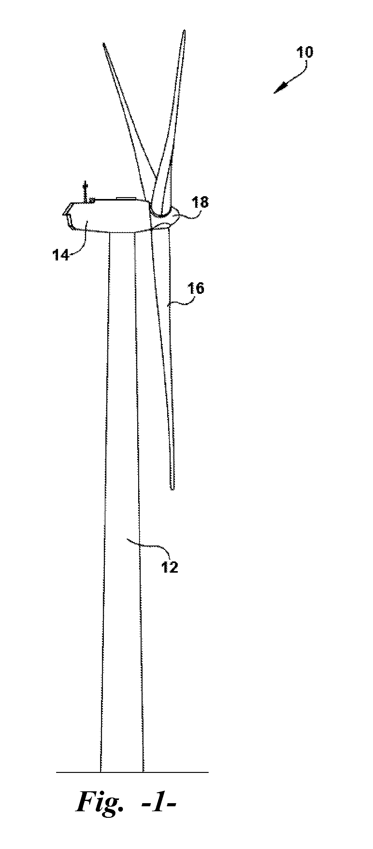
FIG. 1 illustrates a wind turbine 10 of conventional construction. The wind turbine 10 includes a tower 12 with a nacelle 14 mounted thereon. A plurality of turbine blades 16 are mounted to a rotor hub 18, which is in turn connected to a main flange that turns a...


PUM


Abstract

A wind turbine blade has a suction side surface and a pressure side surface. A plurality of dynamic vortex elements are formed on at least one of the suction side or the pressure side surfaces. The vortex elements are activatable between a first retracted position that is inwardly recessed relative to a neutral plane of the surface on which they are formed and a second extended position that is outwardly protruding relative to the neutral plane of the surface.

Description

FIELD OF THE INVENTIONThe present invention relates generally to the field of wind turbines, and more particularly to turbine blades having an aerodynamic surface configuration.BACKGROUND OF THE INVENTIONTurbine blades are the primary elements of wind turbines for converting wind energy into electrical energy. The working principle of the blades resembles that of airplane wings. The blades have the cross-sectional profile of an airfoil such that, during operation, air flows over the blade producing a pressure difference between the sides. Consequently, a lift force, which is directed from a pressure side towards a suction side, acts on the blade. The lift force generates torque on the main rotor shaft, which is geared to a generator for producing electricity.Airflow over the leading edge of the blade is mainly laminar in an “attached-flow” region. The lift force is generated primarily in this attached-flow region. As the air moves towards the trailing edge of the blade, flow separat...

Claims


Application Information

Patent Timeline
Patent Type & Authority Applications(United States)
IPC IPC(8): B64C27/54
CPCF03D1/0633F03D7/022F03D11/00F05B2220/709F05B2240/122Y02E10/723F05B2240/31F05B2240/32F05D2270/17Y02E10/721Y02E10/722F05B2240/30F03D80/00Y02E10/72F05B2240/3062
Inventor XIONG, WEI
Owner GENERAL ELECTRIC CO
Why Eureka
Try Eureka