Sensing apparatus for sensing an object

Active Publication Date: 2011-06-16
KONINKLIJKE PHILIPS ELECTRONICS NV
View PDF14 Cites 26 Cited by
  • Summary
  • Abstract
  • Description
  • Claims
  • Application Information

AI Technical Summary

Benefits of technology

[0003]It is an object of the present invention to provide a sensing apparatus, a sensing method and a corres

Problems solved by technology

The single contact electrode at the distal tip allows measuring the electrical properties of the heart chamber directly on the endocardial surface of the heart chamber, i.e. more accurately than by using the non-contact electrodes, bu

Method used


Image

  • Sensing apparatus for sensing an object
  • Sensing apparatus for sensing an object
  • Sensing apparatus for sensing an object

Examples


Embodiment Construction

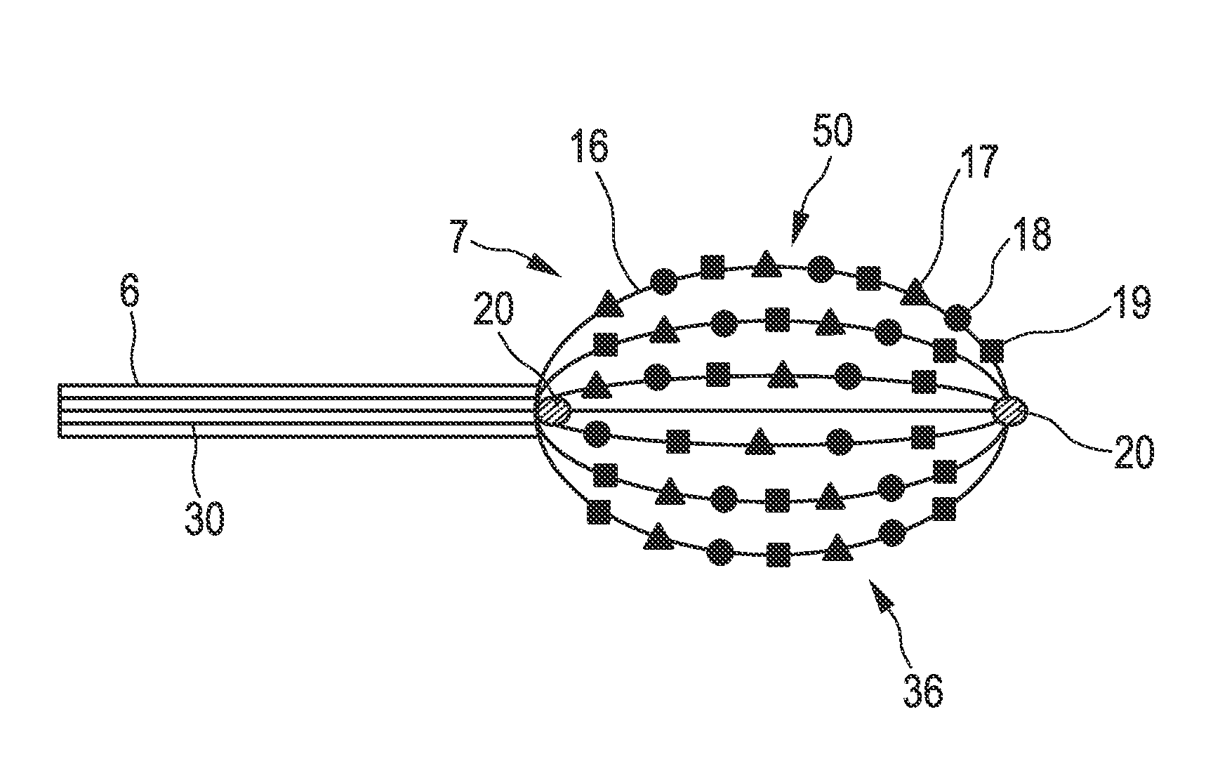
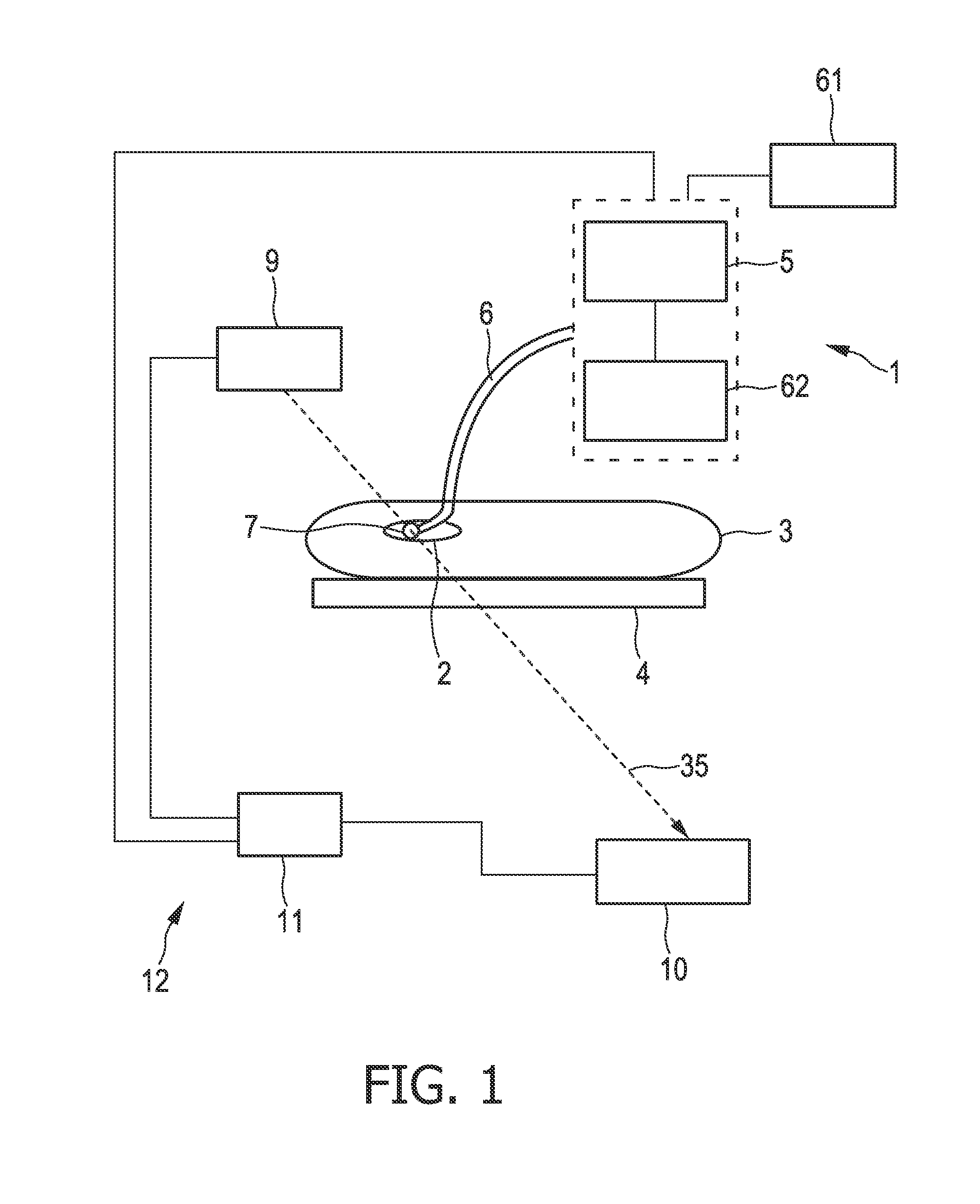
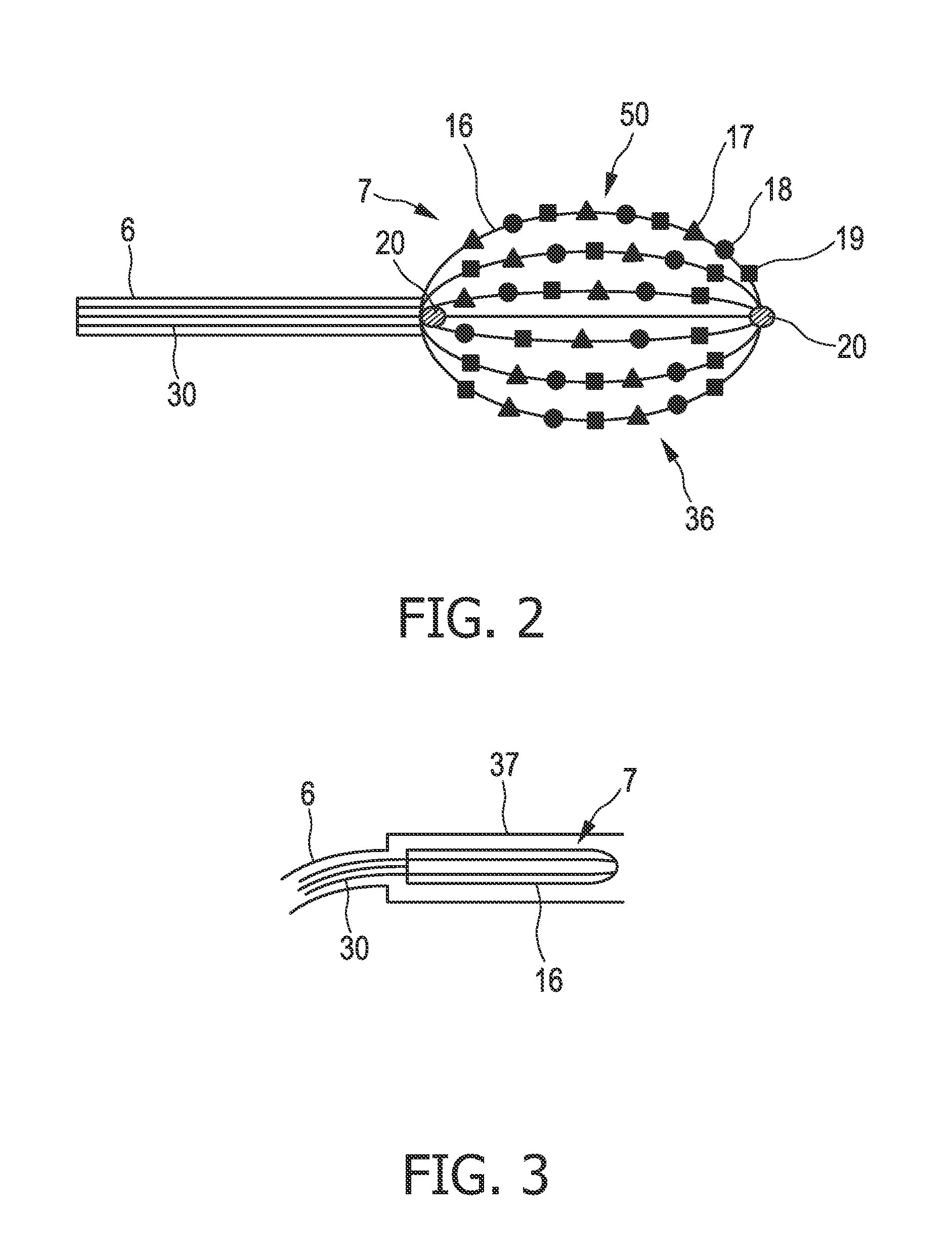
[0048]FIG. 1 shows an apparatus 1 for sensing an object. The apparatus 1 comprises a tube, in this embodiment a catheter 6, and an arrangement 7 of sensing elements for sensing a property of the object. At least some sensing elements of the arrangement 7 are operable in a contact mode, in which a sensing is performable, while the sensing elements are in contact with the object, and in a non-contact mode, in which a sensing is performable, while the sensing elements are not in contact with the object, i.e. the same sensing elements can be operated in the contact mode and in the non-contact mode.

[0049]The arrangement 7 of sensing elements is connected to a control unit 5 via the catheter 6. The catheter 6 with the arrangement 7 of sensing elements can be introduced into an object 2, which is, in this embodiment, a heart of a patient 3 located on a patient table 4, wherein the catheter 6 is steered and navigated to the heart chambers by a steering unit 62 using built-in guiding means (...


PUM


Abstract

The present invention relates to a sensing apparatus for sensing an object, wherein the sensing apparatus (1) comprises an arrangement (7) of sensing elements for sensing a property of the object (2). The sensing elements are operable in a contact mode, in which a sensing is performable, while the sensing elements are in contact with the object (2), and in a non-contact mode, in which a sensing is performable, while the sensing elements are not in contact with the object. The sensing apparatus comprises preferentially further a mode determination unit for determining whether a sensing element is in contact with the object (2) or not.

Description

FIELD OF THE INVENTION[0001]The present invention relates to a sensing apparatus, a sensing method and a corresponding computer program.BACKGROUND OF THE INVENTION[0002]U.S. Pat. No. 6,892,091 B1 discloses an apparatus and a method for generating an electrical map of a chamber of a heart, wherein a catheter is utilized including a body having a proximal end and a distal end. The distal end of the body comprises an arrangement of non-contact electrodes and a distal tip with a contact electrode. The non-contact electrodes are adapted for measuring far field electrical signals in the heart chamber, which allows determining electrical properties with a low spatial and temporal resolution only. The single contact electrode at the distal tip allows measuring the electrical properties of the heart chamber directly on the endocardial surface of the heart chamber, i.e. more accurately than by using the non-contact electrodes, but in order to acquire a map of the endocardial surface showing t...

Claims


Application Information

Patent Timeline
IPC IPC(8): A61B5/042A61B5/0402A61B5/296A61B5/308
CPCA61B5/0422A61B5/0538A61B5/6853A61B2018/00214A61B18/1492A61B18/20A61B2017/00084A61B5/6858A61B5/287
Inventor KAHLERT, JOACHIMBARLEY, MAYA ELLA
Owner KONINKLIJKE PHILIPS ELECTRONICS NV
Why Eureka
Try Eureka