Apparatus and method for sensing target temperature

a technology of target temperature and apparatus, applied in the field of temperature sensing, can solve the problems of data loss, unnecessary current consumption, and circuits not being used for low-power applications, and achieve the effect of more accurate sensing

Inactive Publication Date: 2009-03-10
SAMSUNG ELECTRONICS CO LTD
View PDF6 Cites 3 Cited by
  • Summary
  • Abstract
  • Description
  • Claims
  • Application Information

AI Technical Summary

Benefits of technology

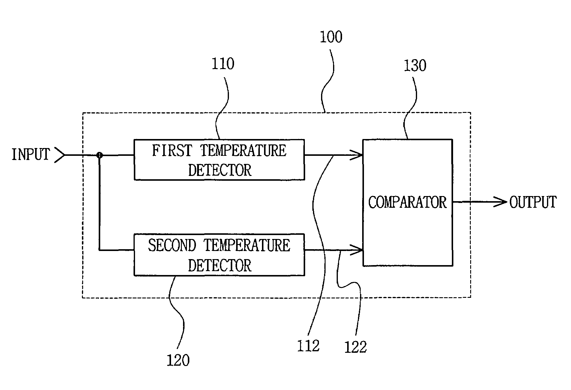
[0017]Accordingly, the present invention provides more accurate sensing of a target temperature by using multiple delay paths having both positive and negative delay characteristics with temperature.
[0024]In this manner, because the first and second temperature detectors provide multiple delay paths with both positive and negative delay changes with temperature, the target temperature that is sensed has smaller deviation with fabrication process variation. Thus, the target temperature may be sensed more accurately.

Problems solved by technology

However, leakage current through a PN junction of a MOS transistor reduces such charge accumulation potentially resulting in data loss.
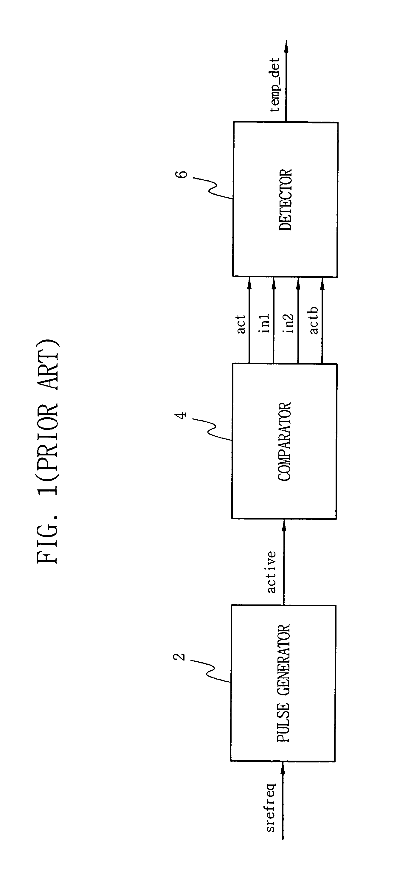
Accordingly, a refresh period is determined based on current leakage at high temperature, but such refresh period is also used at low temperatures resulting in unnecessary current consumption.
However, this circuit is not used for low power applications due to the presence of a threshold voltage of a diode and a cascode type current mirror.
In particular, a diode is difficult to design for good characteristic in a CMOS process.
If trimming points are used for a temperature sensing circuit sensing for a plurality of temperatures, i.e., multi-trimming points, a large resistor, a current mirror, a comparator, and the like are required resulting in difficult implementation.
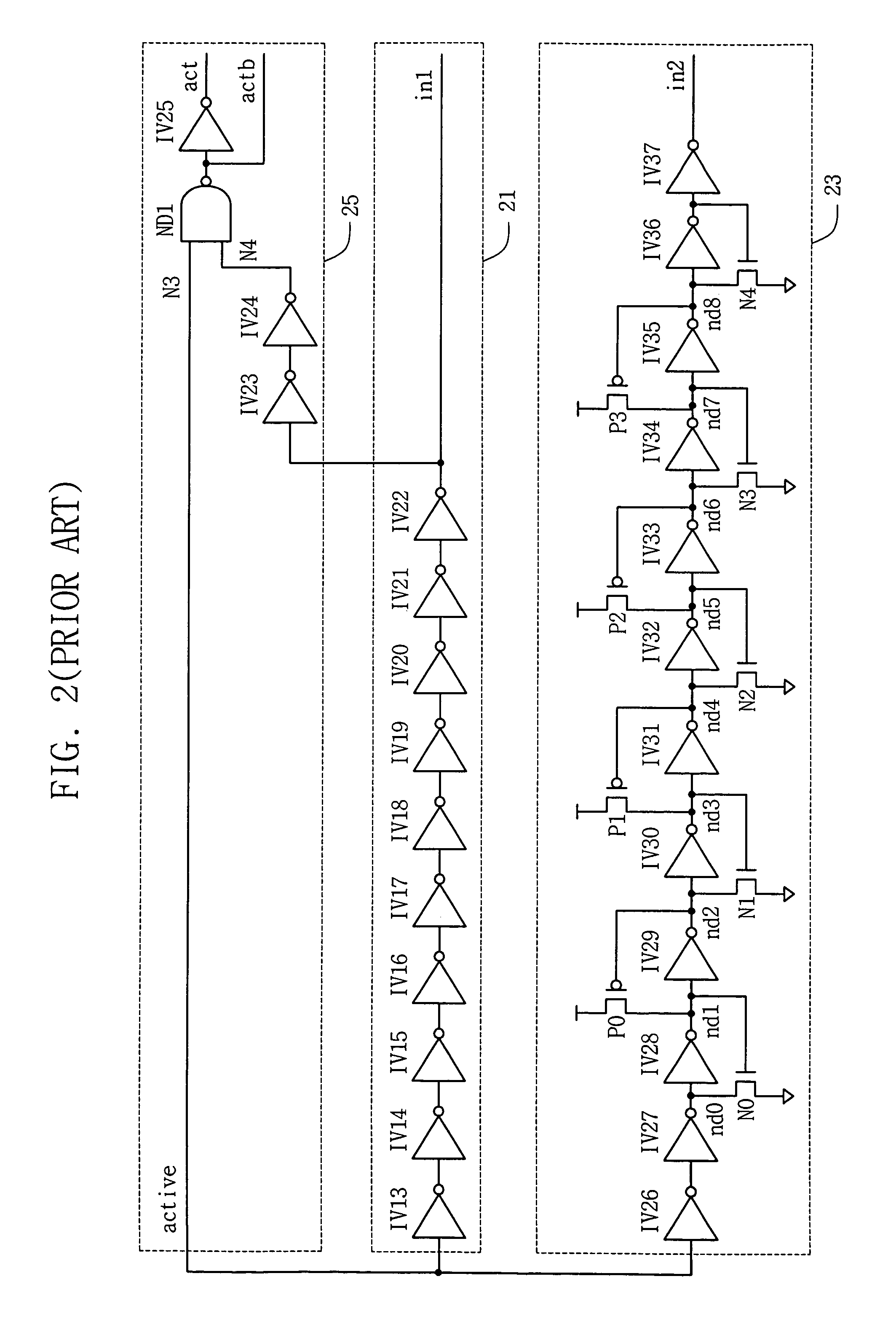
FIG. 3 illustrates that such sensed target temperature varies widely with fabrication process variation such that a target temperature may not be sensed accurately in the prior art.

Method used


Image

  • Apparatus and method for sensing target temperature
  • Apparatus and method for sensing target temperature
  • Apparatus and method for sensing target temperature

Examples


Embodiment Construction

[0041]FIG. 4 shows a circuit diagram of an inverter for analyzing a delay characteristic with temperature for the inverter, according to an embodiment of the present invention. FIG. 5 shows graphs of delay coefficient for different temperatures of the inverter of FIG. 4, according to an embodiment of the present invention.

[0042]The inverter of FIG. 4 is formed with a PMOS transistor PM1 and an NMOS transistor NM1 configured as illustrated in FIG. 4. An inverted output Vout is generated across a load capicitor CL from an input signal Vin. Referring to FIGS. 4 and 5, a delay change with respect to an operating voltage VDD for the inverter increases with temperature below a critical VDD voltage of about 1.3 Volts and decreases with temperature above 1.3 Volts. In addition, the delay change with VDD is positive above 1.3 Volts, and negative below 1.3 Volts.

[0043]FIG. 5 illustrates a delay coefficient SN(G)VDD correlated with delay change that indicates a slope for a graph of delay versu...


PUM


Abstract

For sensing a target temperature, first and second temperature detectors generate first and second delay signals having negative and positive delay changes with temperature. A comparator senses the target temperature from the first and second delay signals such as by activating an output signal when the temperature is at least the target temperature.

Description

BACKGROUND OF THE INVENTION[0001]This application claims priority to Korean Patent Application No. 2005-74254, filed on Aug. 12, 2005 in the Korean Intellectual Property Office, the disclosure of which is incorporated herein in its entirety by reference.[0002]1. Field of the Invention[0003]The present invention relates generally to temperature sensing, and more particularly, to using multiple temperature detectors having positive and negative delay changes with respect to temperature for more accurately sensing a target temperature.[0004]2. Description of the Related Art[0005]In a dynamic random access memory (DRAM) device, data is stored by charge accumulation in a capacitor of a memory cell. However, leakage current through a PN junction of a MOS transistor reduces such charge accumulation potentially resulting in data loss. Accordingly, a refresh operation is performed for restoring the charge accumulation.[0006]The leakage current in a DRAM memory cell generally increases with t...

Claims


Application Information

Patent Timeline
Patent Type & Authority Patents(United States)
IPC IPC(8): G11C7/04
CPCG01K7/00G01K7/425G01N25/20G01K3/08H03K19/00323
Inventor LEE, HOONCHUNG, HOE-JU
Owner SAMSUNG ELECTRONICS CO LTD
Why Eureka
Try Eureka