Capacitive sensor

a capacitive sensor and capacitive technology, applied in the field of capacitive sensors, can solve the problems of increasing manufacturing difficulty, manufacturing cost, easy damage of adhesives, etc., and achieve the effects of simple structure, improved durability, and reduced manufacturing difficulty

Active Publication Date: 2021-08-10
ROBOTOUS CO LTD
View PDF20 Cites 0 Cited by
  • Summary
  • Abstract
  • Description
  • Claims
  • Application Information

AI Technical Summary

Benefits of technology

[0021]According to embodiments of the present invention, the following effects are obtained.
[0022]Manufacture difficulty can be reduced through a simple structure, durability can be improved, and 6-axis forces / torques can be sensed more accurately.
[0023]Effects which may be obtained by the present invention are not limited to the aforementioned effects, and other technical effects not described above may be evidently understood by a person having ordinary skill in the art to which the present invention pertains from the following description.

Problems solved by technology

With respect to such a manufacturing process, problems such as manufacturing cost increase and hardening of an adhesive used to attach strain gauges after a lapse of long time, which causes the adhesive to be easily damaged, are frequently generated.
Although sensors that measure strain of an elastic body through an optical method have been recently developed, a large number of optical components needs to be used therefor and thus manufacture difficulty and manufacturing costs increase.

Method used


Image

  • Capacitive sensor
  • Capacitive sensor
  • Capacitive sensor

Examples


first embodiment

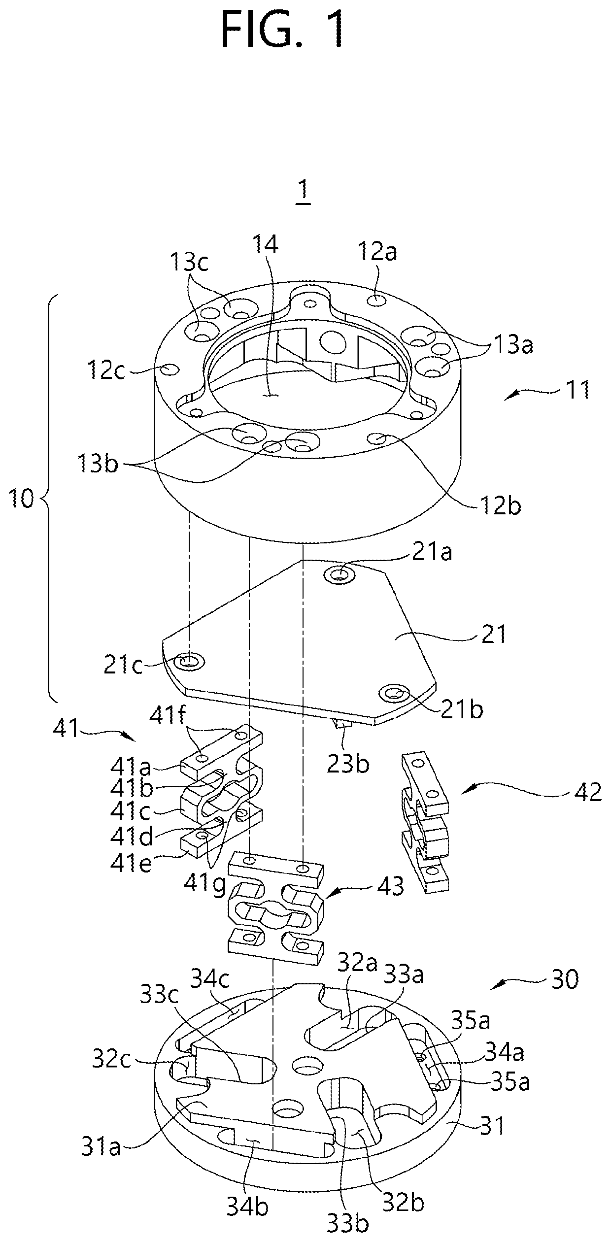
[0045]As shown in FIG. 1, a capacitive sensor 1 according to the present invention includes an upper block 10, a lower block 30 and elastic supports 41, 42 and 43.

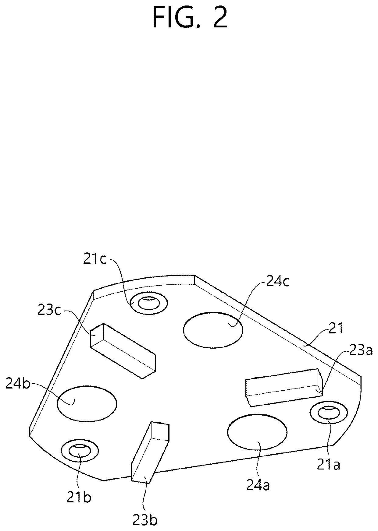
[0046]The upper block 10 includes a housing 11 and a printed circuit board (PCB) 21.

[0047]The housing 11 is formed such that it has an accommodating space 14. The accommodating space 14 may accommodate the PCB 21, the elastic supports 41, 42 and 43 and at least a part of the lower block 30.

[0048]The housing 11 may be combined with the lower block 30. In this case, the housing 11 may be combined with the lower block 30 in such a manner that the bottom of the housing 11 is in contact with the top of a base plate 31 of the lower block 30 or surrounds the side of the base plate 31.

[0049]A plurality of first upper block fixing holes 12a, 12b and 12c and a plurality of first elastic support fixing holes 13a, 13b and 13c may be formed at the top of the housing 11.

[0050]The first upper block fixing holes 12a, 12b and 12c are space...

second embodiment

[0145]As a modified example of the capacitive sensor 2 the upper block 210 and the lower block 230 may be arranged such that the positions thereof are reversed. That is, the lower block 230 in FIGS. 12 and 13 is reversed 180 degrees to serve as an upper block and the upper block 210 is reversed 180 degrees to serve as a lower block.

[0146]In this case, the plurality of lower vertical electrodes 233a, 233b and 233c and the plurality of lower horizontal electrodes 232a, 232b and 232c shown in FIG. 12 serve as upper vertical electrodes and upper horizontal electrodes. In addition, the upper vertical electrodes 223a, 223b and 223c formed on the side of the plate 221 serves as lower vertical electrodes and one side of the plate 221 serves as a lower horizontal electrode.

[0147]That is, in the capacitive sensor according to the modified example, the upper vertical electrodes are formed to protrude from the bottom surface of the upper block and the lower vertical electrodes are formed on th...

third embodiment

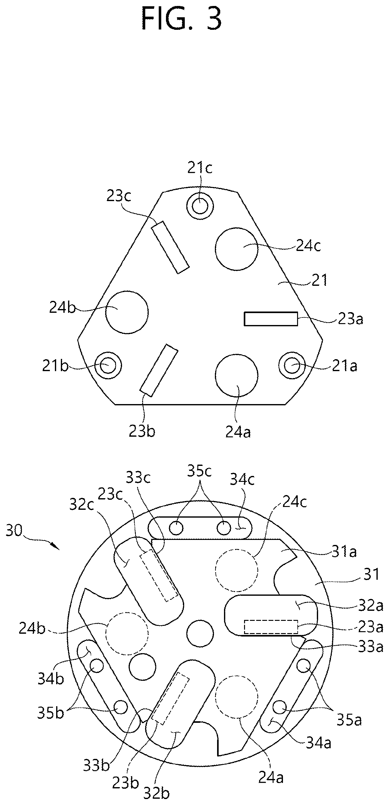
[0150]As shown in FIG. 14, the upper block 310 of the capacitive sensor 3 according to the present invention includes a plurality of upper vertical electrodes 323a, 323b and 323c and a plurality of upper horizontal electrodes 324a, 324b and 324c formed to protrude from the bottom surface of an upper plate 321.

[0151]In addition, the lower block 330 includes a plurality of lower vertical electrodes 333a, 333b and 333c and a plurality of lower horizontal electrodes 332a, 332b and 332c formed to protrude from the top surface of a base plate 331.

[0152]As shown in FIG. 15, the plurality of upper vertical electrodes 323a, 323b and 323c and the plurality of lower vertical electrodes 333a, 333b and 333c partially overlap and are disposed to face each other without being in contact with each other. In addition, the plurality of upper vertical electrodes 323a, 323b and 323c are not in contact with the base plate 331 and the plurality of lower vertical electrodes 333a, 333b and 333c are not in ...


PUM

PropertyMeasurementUnit
capacitancesaaaaaaaaaa
forceaaaaaaaaaa
torqueaaaaaaaaaa

Abstract

A capacitive sensor includes an upper block; a lower block; a plurality of elastic supports for elastically supporting the upper block and the lower block; upper vertical electrodes formed to have faces perpendicular to the bottom surface of the upper block; lower vertical electrodes formed to have faces perpendicular to the top surface of the lower block and disposed to face the upper vertical electrodes such that at least parts of the lower vertical electrodes overlap with the upper vertical electrodes; and an electronic circuit including the upper vertical electrodes and the lower vertical electrodes as parts of the circuit and outputting a signal corresponding to changes in capacitances between the upper vertical electrodes and the lower vertical electrodes caused by a force or a torque applied to at least one of the upper block and the lower block.

Description

CROSS-REFERENCE TO RELATED APPLICATION[0001]This application is a U.S. National Stage of PCT / KR2017 / 012296, filed Nov. 2, 2017, which claims the benefit of Korean Patent Application Nos. 10-2016-0163385, filed on Dec. 2, 2016, in the Korean Intellectual Property Office.TECHNICAL FIELD[0002]The present invention relates to a capacitive sensor, and more specifically, to a capacitive sensor for sensing 6-axis forces / torques using capacitance variations.BACKGROUND ART[0003]Most conventional force / torque sensors use a method of sensing or measuring a force / torque using a strain gauge.[0004]In general, a sensor using a strain gauge includes a pair of external connectors to which an external force is applied, an elastic body which connects the external connectors, and a strain gauge attached to the elastic body to measure strain of the elastic body. The strain gauge senses or measures an external force applied to the external connectors by sensing a resistance that varies according to stra...

Claims


Application Information

Patent Timeline
Patent Type & Authority Patents(United States)
IPC IPC(8): G01L1/04G01D5/241G01L1/14G01L3/00
CPCG01L1/04G01D5/2417G01L1/14G01L3/00G01D5/2412G01L1/142G01L3/1442G01L5/165
Inventor KIM, MIN CHUL
Owner ROBOTOUS CO LTD
Why Eureka
Try Eureka